
LoadILLReflectometry dialog.
Table of Contents
| Name | Direction | Type | Default | Description |
|---|---|---|---|---|
| Filename | Input | string | Mandatory | Name of the Nexus file to load. Allowed extensions: [‘.nxs’] |
| OutputWorkspace | Output | MatrixWorkspace | Mandatory | Name of the output workspace |
| OutputBeamPosition | Output | TableWorkspace | Name of the fitted beam position output workspace | |
| BeamPosition | Input | TableWorkspace | A workspace defining the beam position; used to calculate the Bragg angle | |
| BraggAngle | Input | number | Optional | User defined Bragg angle in degrees |
| XUnit | Input | string | Wavelength | X unit of the OutputWorkspace. Allowed values: [‘Wavelength’, ‘TimeOfFlight’] |
Loads data of a Nexus file obtained from an ILL reflectometry instrument D17 or Figaro into a Workspace2D. Both time-of-flight and monochromatic instrument configurations are supported. In general, this loader reads detector and monitor counts and adds x-axis and error values. The output workspace contains histogram data. The x-axis can have units in time-of-flight or wavelength with non-varying and varying bins, respectively. The conversion to wavelength uses the algorithm ConvertUnits v1. The sample logs associated to the output workspace contain two additional entries, Facility and stheta (unit radian). While Facility is the ILL, the variable stheta is the computed Bragg angle and can serve directly as input for the algorithm ConvertToReflectometryQ v1 if desired.
The chopper values are used for computing the time-of-flight values for the bin edges  by the following equation:

with the following variables: channel width  , time-of-flight delay
  , offset
  , phase of second chopper
  , phase of first chopper
  , open offset
  and velocity of first chopper
  .
.
This loader will update the detector position from what is defined in the instrument definition files. The detector will be moved to the current sample-detector distance and rotated around the origin either on the horizontal or vertical plane.
The rotation angle can be one of the following:
For the direct beam calibration, a direct beam file should be loaded separately and the OutputBeamPosition output property used to obtain a special TableWorkspace containing information on the direct beam position. This workspace can be further given as the BeamPosition input to proceeding loads as exemplified in the following:
LoadILLReflectometry('directbeam.nxs', OutputWorkspace='direct_beam_ws', OutputBeamPosition='beam_position_ws')
LoadILLReflectometry('sample1.nxs', OutputWorkspace='sample1_ws', BeamPosition='beam_position_ws')
LoadILLReflectometry('sample2.nxs', OutputWorkspace='sample2_ws', BeamPosition='beam_position_ws')
# ...
The detector position calibration requires peak position fitting for both the direct and reflected beam data. Basically, the data is integrated using Integration v1, transposed using Transpose v1 and a Gaussian is fitted by Fit v1. The fitted peak position gives the angle between the centre of the detector and the direct or reflected beam:
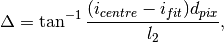
where  is the workspace index of the detector centre (127.5 for D17 and Figaro),
  the fitted peak position,
  the physical pixel width and
  the sample to detector centre distance.
The calibrated detector angle is then given by

where  denotes the detector angles while the subscript
  refers to the reflected beam and
  to the direct beam.
In the case of D17, this loader will move the source position (‘chopper1’ in the instrument definition file) on the z-axis to the position
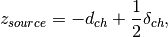
where  is the VirtualChopper.dist_chop_samp sample log entry and
  the Distance.ChopperGap entry.
The following table summarizes the Nexus file entries partially required by the loader: the choice of the chopper is Chopper or VirtualChopper for D17 and two choppers are selected out of four existing choppers for Figaro.
| Nexus entry | D17 | Figaro | Description | Unit |
|---|---|---|---|---|
| acquisition_mode | If time of flight mode or not | - | ||
| data | PSD_data | PSD_data | - | |
| instrument | Chopper1/phase Chopper1/rotation_speed |
CH1/phase CH1/rotation_speed |
chopper phase chopper speed |
degree rpm |
Chopper2/phase Chopper2/rotation_speed |
CH2/phase CH2/rotation_speed |
degree rpm |
||
CH3/phase CH3/rotation_speed |
degree rpm |
|||
CH4/phase CH4/rotation_speed |
degree rpm |
|||
ChopperSetting/firstChopper ChopperSetting/secondChopper |
Number of selected first chopper Number of selected second chopper |
- - |
||
VirtualChopper/chopper1_phase_average VirtualChopper/chopper1_speed_average VirtualChopper/chopper2_phase_average VirtualChopper/chopper2_speed_average |
degree rpm degree rpm |
|||
VirtualChopper/open_offset VirtualChopper/poff |
CollAngle/openOffset CollAngle/poff |
degree degree |
||
det/offset_value det/value |
DTR/offset_value DTR/value |
detector distance offset detector distance value |
millimeter millimeter |
|
PSD/detsize PSD/detsum |
PSD/detsize PSD/detsum |
detector size sum of detector counts |
- - |
|
| PSD/mmpx | PSD/mmpy | pixel width | millimeter | |
PSD/time_of_flight_0 PSD/time_of_flight_1 PSD/time_of_flight_2 |
PSD/time_of_flight_0 PSD/time_of_flight_1 PSD/time_of_flight_2 |
channel width number of channels time-of-flight delay |
microseconds - microseconds |
|
| dan/value | VirtualAxis/DAN_actual_angle | detector angle | degree | |
| san/value | CollAngle/actual_coll_angle | sample angle | degree | |
| monitor1 | data | data | - | |
| monitor2 | data | data | - | |
| theta (Figaro) | sign determines reflection up/down | degree |
Note
To run these usage examples please first download the usage data, and add these to your path. In MantidPlot this is done using Manage User Directories.
Example - Load ILL D17 Nexus file:
# Optional: set facility and default instrument
config['default.facility'] = 'ILL'
config['default.instrument'] = 'D17'

# Load ILL D17 data file (TOF mode) into a workspace 2D using default input options:
ws1 = Load('ILL/D17/317370.nxs')

print("Workspace {} has {} dimensions and {} histograms.").format(ws1.name(), ws1.getNumDims(), ws1.getNumberHistograms())
Output:
Workspace ws1 has 2 dimensions and 258 histograms.
Example - Specify user angle:
import numpy

# Load ILL d17 data file (TOF mode) into a workspace 2D using a user-defined angle of 30 degrees:
ws2 = Load('ILL/D17/317370.nxs', BraggAngle = 5.5)

# The original detector angle can be found in the sample logs:
angleOrig = ws2.getRun().getProperty("dan.value").value

# The Sample Log entry stheta will be the user defined angle of 30 degrees:
angleBragg = ws2.getRun().getProperty("stheta").value * 180. / numpy.pi

print("The detector of workspace {} was rotated to {} degrees.").format(ws2.name(), 2. * angleBragg)
print("The nominal angle in the NeXus file was {:.2} degrees.".format(angleOrig))
Output:
The detector of workspace ws2 was rotated to 5.5 degrees.
The nominal angle in the NeXus file was 3.2 degrees.
Example - Calibration of detector angle by direct beam:
import numpy

directBeamWS = Load('ILL/D17/317369.nxs', OutputBeamPosition='beamPositionWS')

beamPosWS = mtd['beamPositionWS']
peakCentre = beamPosWS.cell('FittedPeakCentre', 0)
print('Fitted direct beam maximum (in workspace indices): {:.5}'.format(peakCentre))

reflectedBeamWS = Load('ILL/D17/317370.nxs', BeamPosition=beamPosWS)

# Lets load the data without detector angle calibration just for reference

refWS = Load('ILL/D17/317370.nxs')

detAngle = numpy.degrees(reflectedBeamWS.getRun().getProperty('stheta').value)
refAngle = numpy.degrees(refWS.getRun().getProperty('stheta').value)

print('Uncalibrated detector angle: {:.4} degrees.'.format(refAngle))
print('Detector angle after calibration using direct beam: {:.4} degrees.'.format(detAngle))
Output:
Fitted direct beam maximum (in workspace indices): 202.18
Uncalibrated detector angle: 1.591 degrees.
Detector angle after calibration using direct beam: 1.627 degrees.
Categories: Algorithms | DataHandling\Nexus