PowderILLEfficiency v1#
Summary#
Performs detector efficiency correction calculation for scanning monochromatic powder diffraction instruments D20 and D2B at ILL.
See Also#
Properties#
Name |
Direction |
Type |
Default |
Description |
|---|---|---|---|---|
CalibrationRun |
Input |
list of str lists |
Mandatory |
File path of calibration runs (numors). Must be detector scans. Allowed values: [‘nxs’] |
CalibrationFile |
Input |
string |
Optional file containing previous calibration constants. Allowed values: [‘nxs’] |
|
CalibrationMethod |
Input |
string |
Median |
The method of how the calibration constant of a pixel is derived from the distribution of ratios. Allowed values: [‘Median’, ‘Mean’, ‘MostLikelyMean’] |
DerivationMethod |
Input |
string |
SequentialSummedReference1D |
Choose sequential for D20 (1D detector), global for D2B (2D detector). Allowed values: [‘SequentialSummedReference1D’, ‘GlobalSummedReference2D’] |
InterpolateOverlappingAngles |
Input |
boolean |
False |
Whether to interpolate scattering angle values in overlapping regions (D20 only). |
NormaliseTo |
Input |
string |
None |
Normalise to monitor or ROI counts before deriving the calibration. Allowed values: [‘None’, ‘Monitor’, ‘ROI’] |
ROI |
Input |
dbl list |
0,100 |
Scattering angle regions of interest for normalisation [degrees]. |
ExcludedRange |
Input |
dbl list |
Scattering angle regions to exclude from the computation of relative calibration constants; for example, the beam stop [degrees]. |
|
PixelRange |
Input |
int list |
1,3072 |
Range of the pixel numbers to compute the calibration factors for (D20 only); for the other pixels outside the range, the factor will be set to 1. |
OutputResponseWorkspace |
Output |
Output workspace containing the summed diffraction patterns of all the overlapping pixels. |
||
OutputWorkspace |
Output |
Mandatory |
Output workspace containing the calibration constants (inverse of efficiency) for each pixel. |
|
NumberOfIterations |
Input |
number |
1 |
Number of iterations to perform (D2B only): 0 means auto; that is, the iterations will terminate after reaching some Chi2/NdoF. |
MaskCriterion |
Input |
dbl list |
Efficiency constants outside this range will be set to zero. |
Description#
This algorithm calculates the detector efficiency corrections for scanning monochromatic powder diffractometers D20 and D2B at ILL. Detector scan in this context stands for a set of discrete rotations of the detector around the sample in the horizontal (scattering) plane. The general philosophy is based on the fact that different detector cells pass through the same spatial coordinates during the scan. Under the assumption that at a certain coordinate all the detectors should measure the same counts, one could derive relative inter-calibration between the cells. The input to the algorithm is a set of detector scan acquisitions recorded for vanadium sample. However, no assumption that vanadium response has to be flat and isotropic, is made. That is, the geometrical effects, off-plane self-attenuation effects, and the small Bragg peaks in the vanadium data are well taken into account. The output is a map of calibration constants that have to be applied multiplicatively to the sample data; that is, the calibration constant is the inverse of the relative detector efficiency.
DerivationMethod#
There are two strategies to derive the efficiencies, as follows:
SequentialSummedReference1D (referred hereafter as the D20 method) must be used for D20, which is a 1D detector with solid rectangular panels.
Takes the first cell response as a function of scattering angle (during the scan) as a reference
Takes the second cell and divides the reference to the second cell response in the overlapping region in terms of scattering angle. This results in an array of relative response ratios.
Uses one of the 3 calibration methods (see below) to compute the relative calibration factor from the array of relative response ratios. This factor is saved in the output as the calibration factor for the second cell.
The response of the second cell is scaled up with that factor, and then merged (in the overlapping region) with the reference using WeightedMean. This results in a new reference.
Repeat from Step 2 for the next cell using the updated reference and so on until the last cell.
For the zero-counting cells, the calibration factor cannot be computed, hence they will be set to 1. Cells are treated as zero-counting if they count zero more than 80% of time.
After the calibration factors are computed for all the cells, they are divided by the median of all the factors (excluding the zero-counting cells), in order to absolutely normalize the calibration curve.
GlobalSummedReference2D (referred hereafter as the D2B method) must be used for D2B, which is a 2D detector composed of PSD tubes that are placed at some distance from each other, hence the detector has gaps between the tubes.
Averages the responses of all the pixels at a certain height level using SumOverlappingTubes. This results in a global reference, which is a 2D matrix of averaged counts.
For each tube, constructs the ratio of the global reference wrt the tube response in the overlapping region; this results in arrays of relative response ratios for each pixel in that tube.
Takes the median of the response ratios as calibration constant for the given pixel in the given tube.
Optionally, if iterations are requested (see below), it applies the calibration of the first run to the input, and repeats from Step 1.
As mentioned, the calibration constants are computed pixel by pixel; no grouping of pixels inside the tubes is done.
CalibrationMethod#
When relative response ratios are constructed for a given pixel, the algorithm offers 3 ways to get the calibration factor out: median (default), mean and MostLikelyMean. For the D2B case, for the moment only median is supported, as the convergence of the other methods through the iterations is currently under investigation.
CalibrationRun#
The input must be a set of detector-scan numors in .nxs format produced for vanadium.
CalibrationFile#
Optionally a previously derived calibration file (e.g. the output of this algorithm saved with SaveNexusProcessed) can be provided. In this case this calibration will be applied first, and then the algorithm will compute residual calibration factors on top of that.
ExcludedRange#
Provide ranges in scattering angle in degrees (in equatorial plane) to exclude non-desired regions, e.g. the beam stop. In principle, multiple regions can be set, -20,0,10,20 will exclude [-20,0] and [10,20]. The exclusion happens at Step 3 for both of the derivation methods, before computing the calibration factor out of the relative response ratios.
PixelRange#
Provide the range of detector cells to compute the calibration factors for. For the rest of the cells, the factor will be set to 1. This is used for D20 only, and by default the factors will be computed for all the cells.
NormaliseTo#
The input data can be optionally normalised to monitor counts or region-of-interest (ROI, for D20 only) counts.
ROI#
Regions of scattering angle in degrees (in equatorial plane), where the counts are summed, and the data is normalised to the sum. Relevant only for D20.
OutputWorkspace#
For D20, the output is a single-column workspace containing the calibration factors for each cell. For D2B, it is a 2D workspace (x axis is the tube index, spectrum axis is the pixel index in the tube). The output should be normally saved with SaveNexusProcessed to be later used in PowderILLParameterScan and PowderILLDetectorScan.
OutputResponseWorkspace#
Optionally, the merged response of the cells taking into account the newly derived calibration can be output. This is a 1D spectrum for D20 and 2D workspace for D2B.
NumberOfIterations#
This is used for D2B only. For D20 there is no need for iterations, since a single shot derivation is already convergent; that is, the residual calibration factors are identical to unity.
This specifies how many times the calibration has to be derived (see Step 4 above for D2B method):
1 by default: The calibration will be derived only once (single-shot) and no iteration will be performed. Typically this gives reasonably good result already.
User specified positive integer: Iterations will be performed as many times as requested. It is not advised to iterate too much, since after local convergence it may start to diverge again; hence there is a hard limit of 10.
0 stands for auto: Iterations will be run automatically until the termination criteria is satisfied. Termination criteria is:
\[\frac{\chi^{2}}{NdoF} = \frac{\sum_{i,j}(c_{ij} - 1)^{2}}{N_{\mathrm{tubes}} * N_{\mathrm{pixels\_per\_tube}}} < t\]where \(c_{ij}\) is the residual calibration factor for tube i and pixel j, \(t\) is the threshold defined in Instrument Parameter File (IPF) as chi2_ndof.
The top and bottom parts of the tubes are excluded from this calculation. How many pixels exactly are excluded is again defined in IPF as pixels_to_trim.
Currently, for D2B, pixels_to_trim=28 and t=1%. With this settings iterations typically terminate after the first one, i. e. one run and one iteration give results already convergent within 1%.
This has to be interpreted as: the residual calibration is close enough to unity, so further iterations will not change the calibration much.
However, this criterion does not prevent from divergence in all the cases. It can happen that for a given pixel the residual calibration factor (albeit close to unity) is always on the same side (i.e. always above 1 or below 1); this will cause the absolute calibration to gradually diverge with iterations. Anyways, the method implemented does not provide enough precision to resolve residual calibration better than in the percent range. Hence, care must be taken when using the iterations. It is not recommended to use more than 2 iterations.
MaskCriterion#
Provide a range, out of which the calibration constants will be set to zero. This effectively masks the pixels after applying the calibration multiplicatively.
Limitations#
For D2B it is assumed that the tubes and pixels pass through the exact same positions during the scan. That is, the tubes have to be aligned vertically and horizontally and the gap between each pair of neighboring tubes must be integer multiple of the scan step. If some of the input files will have 26 scan points instead of 25, the last scan point data will be ignored.
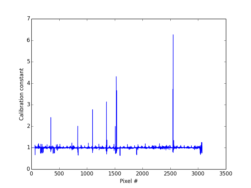
D20 Workflow#

Note
To run these usage examples please first download the usage data, and add these to your path. In Mantid this is done using Manage User Directories.
Example - D20
import matplotlib.pyplot as plt
from mantid import plots
from mantid.simpleapi import PowderILLEfficiency
PowderILLEfficiency(CalibrationRun='967076.nxs', DerivationMethod='SequentialSummedReference1D', OutputWorkspace='calib')
Transpose(InputWorkspace='calib', OutputWorkspace='calib')
fig, ax = plt.subplots(subplot_kw={'projection':'mantid'})
ax.plot(mtd['calib'],'-')
ax.set_xlabel('Pixel #')
ax.set_ylabel('Calibration constant')
fig.show()
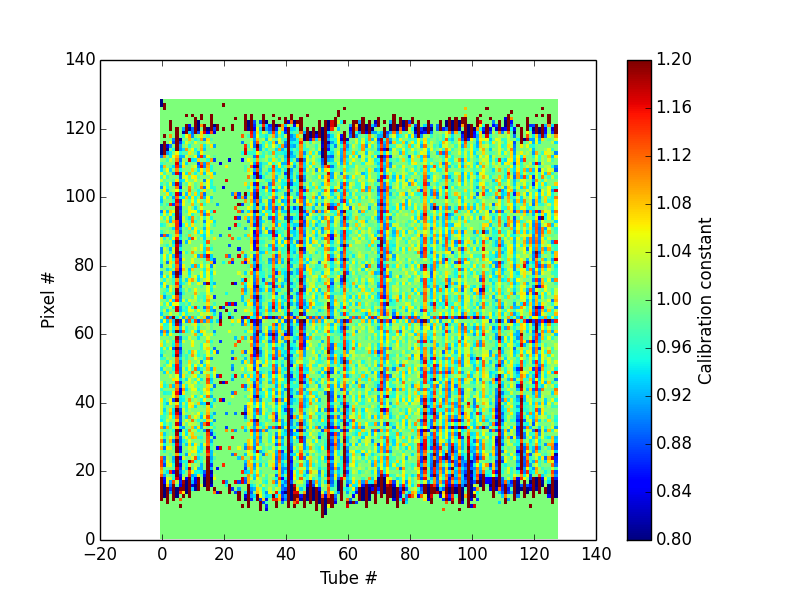
D2B Workflow#

Example - D2B
import matplotlib.pyplot as plt
from mantid import plots
from mantid.simpleapi import PowderILLEfficiency
PowderILLEfficiency(CalibrationRun='532008,532009', DerivationMethod='GlobalSummedReference2D', OutputWorkspace='calib')
fig, ax = plt.subplots(subplot_kw={'projection':'mantid'})
c = ax.pcolormesh(mtd['calib'], vmin=0.8, vmax=1.2)
ax.set_xlabel('Tube #')
ax.set_ylabel('Pixel #')
cbar = fig.colorbar(c)
cbar.set_label('Calibration constant')
fig.show()
Source#
Python: PowderILLEfficiency.py