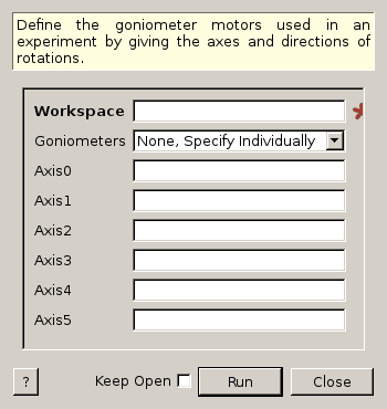
SetGoniometer dialog.
Table of Contents
Define the goniometer motors used in an experiment by giving the axes and directions of rotations.
| Name | Direction | Type | Default | Description |
|---|---|---|---|---|
| Workspace | InOut | MatrixWorkspace | Mandatory | An workspace that will be modified with the new goniometer created. |
| Goniometers | Input | string | None, Specify Individually | Set the axes and motor names according to goniometers that we define in the code (Universal defined for SNS). Allowed values: [‘None, Specify Individually’, ‘Universal’] |
| Axis0 | Input | string | Axis0: name, x,y,z, 1/-1 (1 for ccw, -1 for cw rotation). A number of degrees can be used instead of name. Leave blank for no axis | |
| Axis1 | Input | string | Axis1: name, x,y,z, 1/-1 (1 for ccw, -1 for cw rotation). A number of degrees can be used instead of name. Leave blank for no axis | |
| Axis2 | Input | string | Axis2: name, x,y,z, 1/-1 (1 for ccw, -1 for cw rotation). A number of degrees can be used instead of name. Leave blank for no axis | |
| Axis3 | Input | string | Axis3: name, x,y,z, 1/-1 (1 for ccw, -1 for cw rotation). A number of degrees can be used instead of name. Leave blank for no axis | |
| Axis4 | Input | string | Axis4: name, x,y,z, 1/-1 (1 for ccw, -1 for cw rotation). A number of degrees can be used instead of name. Leave blank for no axis | |
| Axis5 | Input | string | Axis5: name, x,y,z, 1/-1 (1 for ccw, -1 for cw rotation). A number of degrees can be used instead of name. Leave blank for no axis |
Use this algorithm to define your goniometer. Enter each axis in the order of rotation, starting with the one farthest from the sample.
You may enter up to 6 axes, for which you must define (separated by commas):
The run’s sample logs will be used in order to determine the actual angles of rotation: for example, if you have an axis called ‘phi’, then the first value of the log called ‘phi’ will be used as the rotation angle. Units are assumed to be degrees.
The “Universal” goniometer at SNS is equivalent to Axis0 tied to the “omega” log pointing vertically upward, Axis1 tied to “chi” log, pointing along the beam, and Axis2 tied to “phi”, pointing vertically upward.
SetGoniometer(w,”Universal”) is the same as SetGoniometer(w,Axis0=”omega,0,1,0,1”,Axis1=”chi,0,0,1,1”,Axis2=”phi,0,1,0,1”)
wg=CreateSingleValuedWorkspace()
AddSampleLog(wg,"Motor1","45.","Number")
SetGoniometer(wg,Axis0="Motor1,0,1,0,1",Axis1="5,0,1,0,1")

print "Log values:",wg.getRun().keys()
print "Goniometer angles: ",wg.getRun().getGoniometer().getEulerAngles('YZY')
print "Clearing goniometer up"
SetGoniometer(wg)
print "Goniometer angles: ",wg.getRun().getGoniometer().getEulerAngles('YZY')
Output:
Log values: ['Motor1', 'GoniometerAxis1_FixedValue']
Goniometer angles:  [50,0,0]
Clearing goniometer up
Goniometer angles:  [0,0,0]
Categories: Algorithms | Crystal\Goniometer