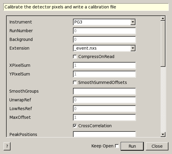
CalibrateRectangularDetectors dialog.
Table of Contents
| Name | Direction | Type | Default | Description |
|---|---|---|---|---|
| Instrument | Input | string | PG3 | Allowed values: [‘NOM’, ‘BSS’, ‘SNAP’, ‘CNCS’, ‘VULCAN’, ‘CORELLI’, ‘PG3’, ‘MANDI’, ‘TOPAZ’, ‘VIS’, ‘SEQ’, ‘ARCS’] |
| RunNumber | Input | int list | 0 | |
| Background | Input | int list | 0 | |
| Extension | Input | string | _event.nxs | Allowed extensions: [‘_event.nxs’, ‘_runinfo.xml’, ‘.nxs.h5’] |
| CompressOnRead | Input | boolean | False | Compress the event list when reading in the data |
| XPixelSum | Input | number | 1 | Sum detector pixels in X direction. Must be a factor of X total pixels. Default is 1. |
| YPixelSum | Input | number | 1 | Sum detector pixels in Y direction. Must be a factor of Y total pixels. Default is 1. |
| SmoothSummedOffsets | Input | boolean | False | If the data was summed for calibration, smooth the resulting offsets workspace. |
| SmoothGroups | Input | string | Comma delimited number of points for smoothing pixels in each group. Default is no Smoothing. | |
| UnwrapRef | Input | number | 0 | Reference total flight path for frame unwrapping. Zero skips the correction |
| LowResRef | Input | number | 0 | Reference DIFC for resolution removal. Zero skips the correction |
| MaxOffset | Input | number | 1 | Maximum absolute value of offsets; default is 1 |
| CrossCorrelation | Input | boolean | True | CrossCorrelation if True; minimize using many peaks if False. |
| PeakPositions | Input | dbl list | Comma delimited d-space positions of reference peaks. Use 1-3 for Cross Correlation. Unlimited for many peaks option. | |
| PeakWindowMax | Input | number | 0 | Maximum window around a peak to search for it. Optional. |
| FitwindowTableWorkspace | Input | TableWorkspace | Name of input table workspace containing the fit window information for each spectrum. | |
| MinimumPeakHeight | Input | number | 2 | Minimum value allowed for peak height |
| MinimumPeakHeightObs | Input | number | 0 | Minimum value of a peak’s maximum observed Y value for this peak to be used to calculate offset. |
| DetectorResolutionWorkspace | Input | MatrixWorkspace | Name of optional input matrix workspace for each detector’s resolution (D(d)/d). | |
| AllowedResRange | Input | dbl list | 0.25,4 | Range of allowed individual peak’s resolution factor to input detector’s resolution. |
| PeakFunction | Input | string | Gaussian | Type of peak to fit. Used only with CrossCorrelation=False. Allowed values: [‘BackToBackExponential’, ‘Gaussian’, ‘Lorentzian’] |
| BackgroundType | Input | string | Flat | Used only with CrossCorrelation=False. Allowed values: [‘Flat’, ‘Linear’, ‘Quadratic’] |
| DetectorsPeaks | Input | int list | Comma delimited numbers of detector banks for each peak if using 2-3 peaks for Cross Correlation. Default is all. | |
| PeakHalfWidth | Input | number | 0.05 | Half width of d-space around peaks for Cross Correlation. Default is 0.05 |
| CrossCorrelationPoints | Input | number | 100 | Number of points to find peak from Cross Correlation. Default is 100 |
| Binning | Input | dbl list | 0,0,0 | Min, Step, and Max of d-space bins. Logarithmic binning is used if Step is negative. |
| DiffractionFocusWorkspace | Input | boolean | False | Diffraction focus by detectors. Default is False |
| GroupDetectorsBy | Input | string | All | Detector groups to use for future focussing: All detectors as one group, Groups (East,West for SNAP), Columns for SNAP, detector banks. Allowed values: [‘All’, ‘Group’, ‘Column’, ‘bank’] |
| FilterBadPulses | Input | boolean | True | Filter out events measured while proton charge is more than 5% below average |
| FilterByTimeMin | Input | number | 0 | Relative time to start filtering by in seconds. Applies only to sample. |
| FilterByTimeMax | Input | number | 0 | Relative time to stop filtering by in seconds. Applies only to sample. |
| SaveAs | Input | string | calibration | Allowed values: [‘dspacemap’, ‘calibration’, ‘dspacemap and calibration’] |
| OutputDirectory | Input | string | Mandatory | |
| OutputFilename | Output | string |
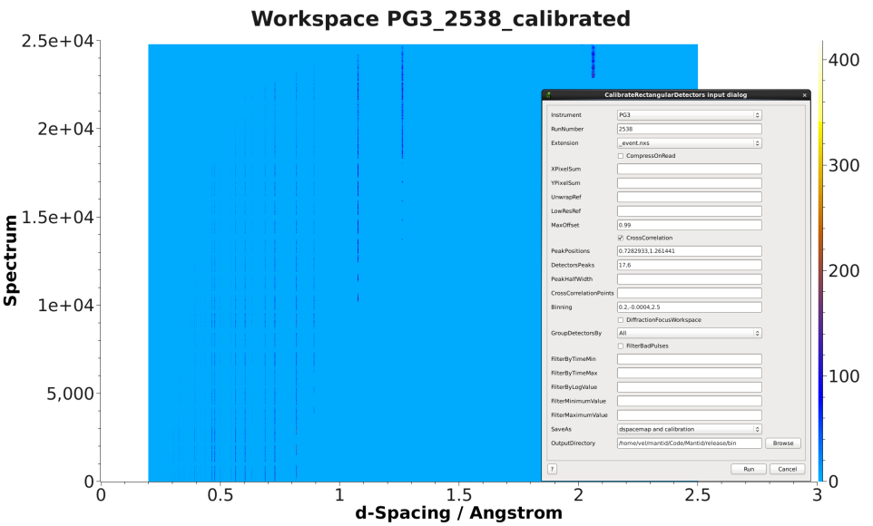
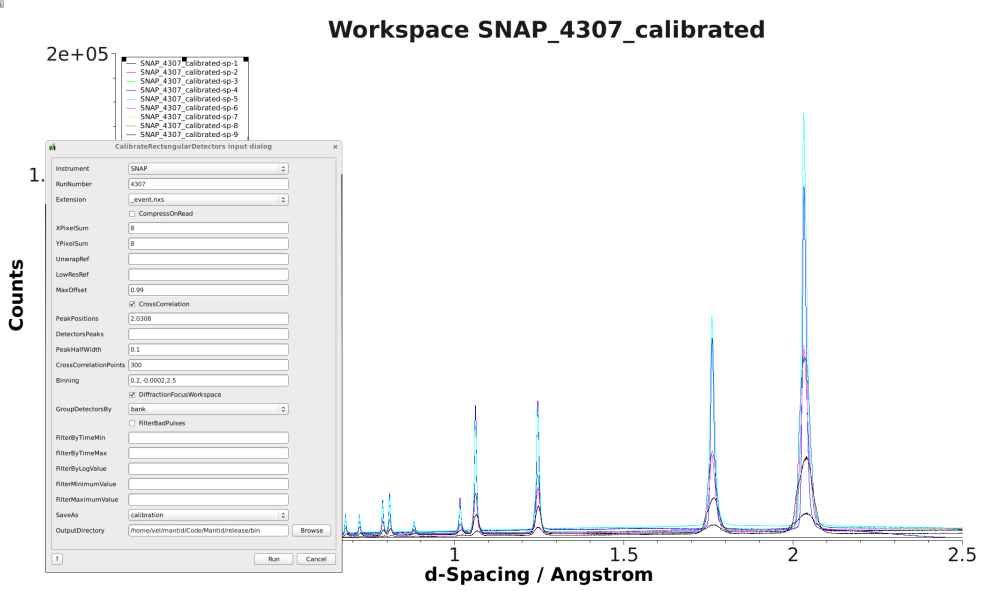
Here are examples of input and output from PG3 and SNAP:
The purpose of this algorithm is to calibrate the detector pixels and write a calibration file. The calibration file name contains the instrument, run number, and date of calibration. A binary Dspacemap file that converts from TOF to d-space including the calculated offsets is also an output option. For CrossCorrelation option: If one peak is not in the spectra of all the detectors, you can specify the first n detectors to be calibrated with one peak and the next n detectors to be calibrated with the second peak. If a color fill plot of the calibrated workspace does not look good, do a color fill plot of the workspace that ends in cc (cross correlation) to see if the CrossCorrelationPoints and/or PeakHalfWidth should be increased or decreased. Also plot the reference spectra from the cc workspace.
There are two exclusive approaches to define peak’s fit-window.
Optional input property DetectorResolutionWorkspace is a matrix
workspace containing the detector resolution  for
each spectrum. Combining with property AllowedResRange, it defines the
lower and upper limit for accepted fitted peak width.
for
each spectrum. Combining with property AllowedResRange, it defines the
lower and upper limit for accepted fitted peak width.
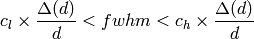
Let ![c_l = AllowedResRange[0]](../_images/math/e3fbaff04fca5b8205d614dde7e376c632bf9aa0.png) ,
, ![c_h = AllowedResRange[1]](../_images/math/a15efbd13d3735bc60948a7e0b1d5e1172c90efd.png) and
and  as the peak’s fitted width. Then,
See also
Algorithm EstimateResolutionDiffraction v1
Categories: Algorithms | Diffraction\Calibration