\(\renewcommand\AA{\unicode{x212B}}\)
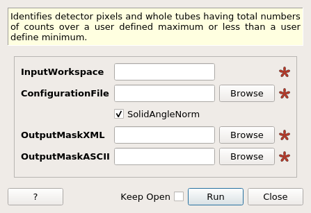
NOMADMedianDetectorTest dialog.
Table of Contents
Identifies detector pixels and whole tubes having total numbers of counts over a user defined maximum or less than a user define minimum.
| Name | Direction | Type | Default | Description |
|---|---|---|---|---|
| InputWorkspace | Input | Workspace | Mandatory | Workspace containing reference pixel intensities |
| ConfigurationFile | Input | string | Mandatory | YML file specifying collimation states and unused eight-packs. Allowed extensions: [‘.yml’] |
| SolidAngleNorm | Input | boolean | True | Normalize each pixel by its solid angle? |
| OutputMaskXML | Input | string | Mandatory | Output masked pixels in XML format. Allowed extensions: [‘.xml’] |
| OutputMaskASCII | Input | string | Mandatory | Output masked pixels in single-column ASCII file. Allowed extensions: [‘.txt’] |
Algorithm to mask detector pixels showing deficient or excessive neutron counts. The deficit and excess is referenced to the median calculated over intensities in a single tube, an eight-pack, or a panel of eight-packs. The prescription for the median calculation depends on the collimation level of the eigh-pack to which a particular detector belongs to.
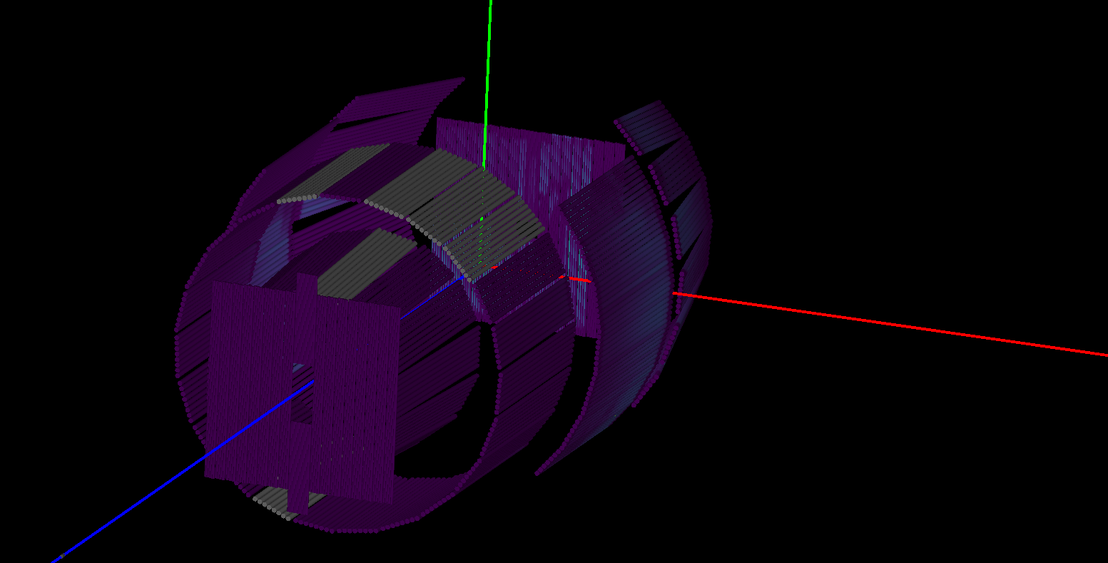
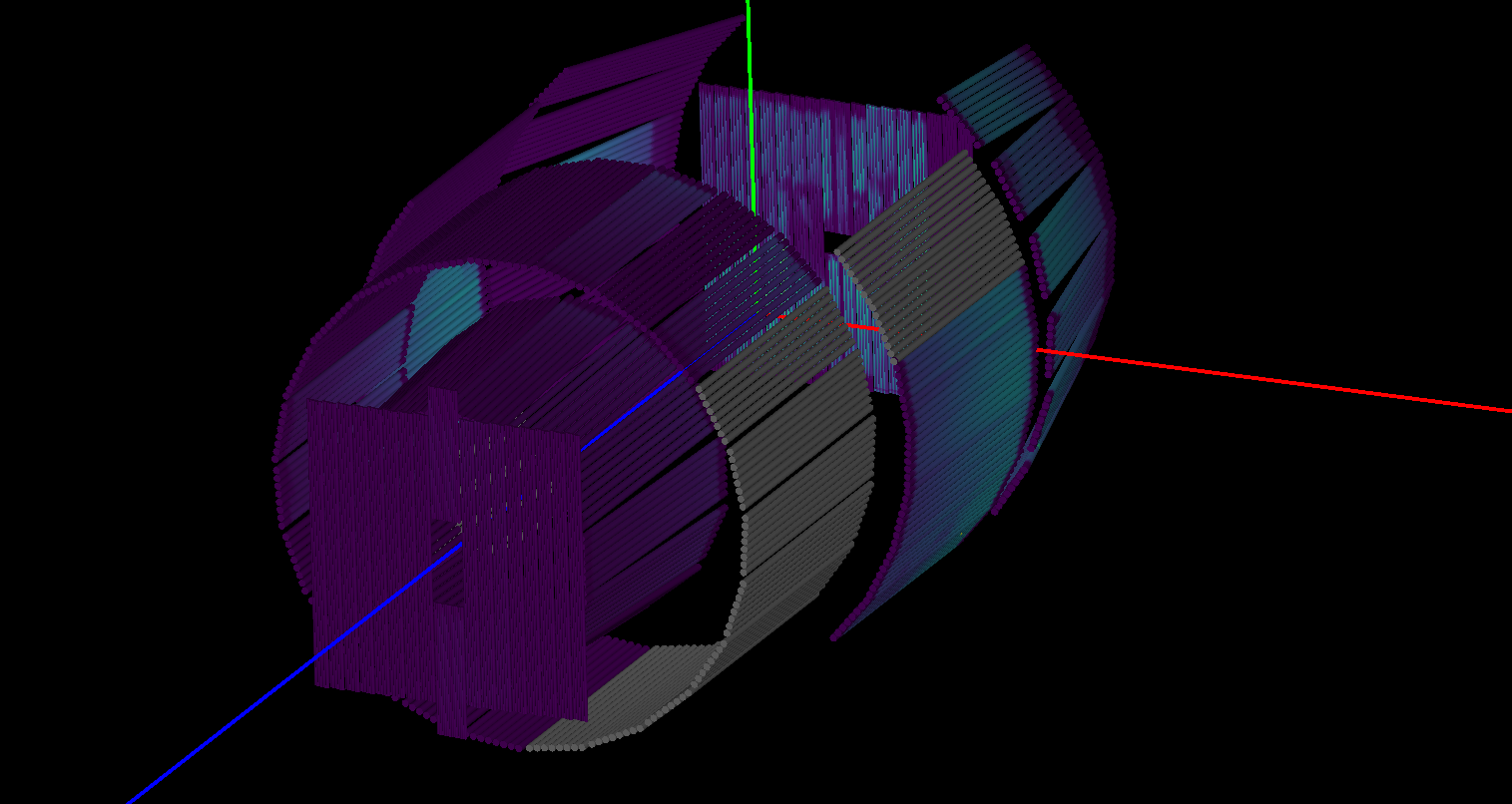
The full-collimated and half-collimated eight-packs are presented in picture below, respectively. Those grey-colored tubes are full-collimated (in the first picture) or half-collimated (in the second picture).
The following workflow presents the prescription to mask a detector pixel according to the median taken over the pixel intensity in a tube. For tubes in eight-packs with a Half-collimation level, the median is taken over the first half of the tube to test the pixels in this half. Analogously, the median is taken over the second half of the tube to test the pixels in the second half.
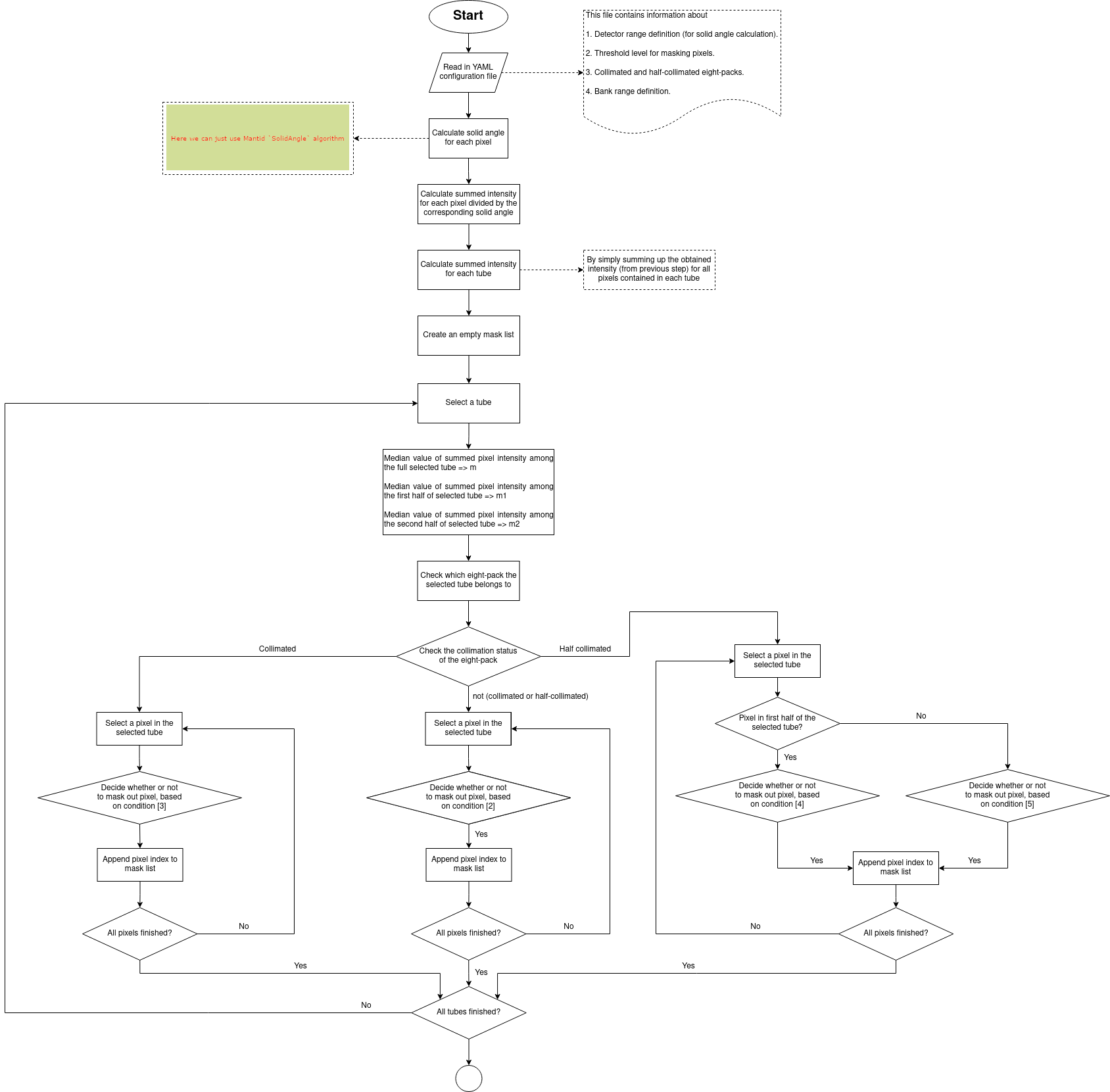
In the inequalities below, \(I\) is the pixel intensity, \(m\) is the median over the tube, and \(f_{lp} < 1\) and \(f_{up} > 1\) are multiplicative factors to set the minimum and maximum intensity thresholds.
Condition [2] \(I < f_{lp} \cdot m\) or \(I > f_{up} \cdot m\)
Condition [3] \(I < (1 + 3(f_{lp} - 1)) m\) or \(I > (1 + 3(f_{up} - 1)) m\)
In the inequalities below, \(m_1\) and \(m_1\) are the median taken over the first and second half of the tube.
Condition [4] \(I < (1 + 3(f_{lp} - 1)) m_1\) or \(I > (1 + 3(f_{up} - 1)) m_1\)
Condition [5] \(I < (1 + 3(f_{lp} - 1)) m_2\) or \(I > (1 + 3(f_{up} - 1)) m_2\)
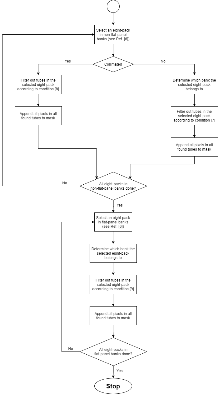
Pixels can also be masked if they fail the median test where the median is calculated from the intensities of their corresponding eight-pack (if the eight-pack is fully collimated) or the median of their corresponding panel (if the eight-pack is not fully collimated).
the following workflow prescribes the calculation of the median for each of the instrument panels (termed as “banks” in the workflow picture)
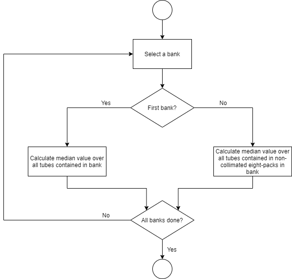
Finally, the following workflow prescribes the test using the eight-pack mediam or the panel median criterium
Reference [6] The first four Panels (a.k.a Banks) are “non-flat”, and the last two are “flat”.
In the inequalities below, \(I\) is the pixel intensity and \(m_B\) is the median over the Panel (a.k.a “Bank”), \(m_{8P}\) is the median over the eight-pack. Multiplicative factors \(f_{lb} < 1\) and \(f_{ub} > 1\) set the minimum and maximum intensity thresholds.
Condition [7] \(I < f_{lB} \cdot m_B\) or \(I > f_{pB} \cdot m_B\)
Condition [8] \(I < f_{lB} \cdot m_{8P}\) or \(I > f_{pB} \cdot m_{8P}\)
Condition [9] \(I < 0.1 \cdot m_B\)
Eight-Packs in use, their collimation level, as well as multiplicative factors \(f_{lp}\) (“low_pixel”), \(f_{up}\) (“high_pixel”), \(f_{lb}\) (“low_tube”), and \(f_{ub}\) (“high_tube”) are specified in a configuration file in YML format. Here’s the relevant portion of one such file:
#
# This block specifies the threshold (relative to median integrated
# intensity of either pixel or tube) for masking out pixels.
#
threshold:
low_pixel: 0.9
high_pixel: 1.2
low_tube: 0.7
high_tube: 1.3
#
# Indexes of eight-packs in use.
# eight_packs: [3,7,8,9,10,11,19,20,26,28,30,34,38,39,40,41,44,45,46,47,48,49,50,54,57,58,59,60,61,62,63,64,65,66,67,68,69,70,71,72,73,74,75,76,77,89,90,93,94,95]
#
# This block specifies the full and half collimated eight-packs.
# Notice: Indexes represent indexes of the “eight_packs” list
#
collimation:
full_col: [1, 8, 16, 25, 27, 28, 29]
half_col: [30, 31, 32, 33, 34, 35, 36, 37, 38, 39, 45, 46]