\(\renewcommand\AA{\unicode{x212B}}\)
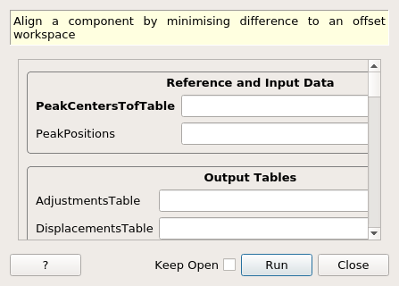
AlignComponents dialog.
Table of Contents
| Name | Direction | Type | Default | Description |
|---|---|---|---|---|
| PeakCentersTofTable | Input | TableWorkspace | Mandatory | Table of found peak centers, in TOF units |
| PeakPositions | Input | dbl list | Comma separated list of reference peak center d-spacings, sorted by increasing value. | |
| AdjustmentsTable | Input | string | Name of output table containing optimized locations and orientations for each component | |
| DisplacementsTable | Input | string | Name of output table containing changes in position and euler angles for each bank component | |
| MaskWorkspace | Input | MatrixWorkspace | Mask workspace | |
| InstrumentFilename | Input | string | Instrument filename. Allowed extensions: [‘.xml’] | |
| InputWorkspace | Input | Workspace | Workspace containing the instrument to be calibrated | |
| OutputWorkspace | Output | Workspace | Mandatory | Workspace containing the calibrated instrument |
| FitSourcePosition | Input | boolean | False | Fit the source position, changes L1 (source to sample) distance. Uses entire instrument. Occurs before Components are Aligned. |
| FitSamplePosition | Input | boolean | False | Fit the sample position, changes L1 (source to sample) and L2 (sample to detector) distance.Uses entire instrument. Occurs before Components are Aligned. |
| ComponentList | Input | str list | Comma separated list on instrument components to refine. | |
| Xposition | Input | boolean | False | Refine Xposition of source and/or sample and/or components |
| MinXposition | Input | number | -0.1 | Minimum relative X bound (m) |
| MaxXposition | Input | number | 0.1 | Maximum relative X bound (m) |
| Yposition | Input | boolean | False | Refine Yposition of source and/or sample and/or components |
| MinYposition | Input | number | -0.1 | Minimum relative Y bound (m) |
| MaxYposition | Input | number | 0.1 | Maximum relative Y bound (m) |
| Zposition | Input | boolean | False | Refine Zposition of source and/or sample and/or components |
| MinZposition | Input | number | -0.1 | Minimum relative Z bound (m) |
| MaxZposition | Input | number | 0.1 | Maximum relative Z bound (m) |
| EulerConvention | Input | string | YZX | Euler angles convention used when calculating and displaying angles,eg XYZ corresponding to alpha beta gamma. Allowed values: [‘ZXZ’, ‘XYX’, ‘YZY’, ‘ZYZ’, ‘XZX’, ‘YXY’, ‘XYZ’, ‘YZX’, ‘ZXY’, ‘XZY’, ‘ZYX’, ‘YXZ’] |
| AlphaRotation | Input | boolean | False | Refine rotation around first axis, alpha, for the components |
| MinAlphaRotation | Input | number | -10 | Minimum relative alpha rotation (deg) |
| MaxAlphaRotation | Input | number | 10 | Maximum relative alpha rotation (deg) |
| BetaRotation | Input | boolean | False | Refine rotation around seconds axis, beta, for the components |
| MinBetaRotation | Input | number | -10 | Minimum relative beta rotation (deg) |
| MaxBetaRotation | Input | number | 10 | Maximum relative beta rotation (deg) |
| GammaRotation | Input | boolean | False | Refine rotation around third axis, gamma, for the components |
| MinGammaRotation | Input | number | -10 | Minimum relative gamma rotation (deg) |
| MaxGammaRotation | Input | number | 10 | Maximum relative gamma rotation (deg) |
| Minimizer | Input | string | L-BFGS-B | Minimizer to Use. Allowed values: [‘L-BFGS-B’, ‘differential_evolution’] |
| MaxIterations | Input | number | 100 | Maximum number of iterations for minimizer differential_evolution |
This algorithm will take a table of peak-center positions (TOF units) for every pixel, and minimize the following quantity by moving and rotating instrument components.
where the sums is for all \(N_d\) detector pixels in a given instrument component and all \(M_i\) peak centers observed at detector pixel \(i\). The quantity to be summed is the absolute value of the fractional difference between the observed peak center in d-spacing units for detector pixel \(i\) and peak \(j\), \(DIFC_i * TOF_{i,j}\), and a reference experimental value for the d-spacing of peak \(j\), \(d^{exp}_j\). The conversion from peak center in TOF units (\(TOF_{i,j}\)) to d-spacing units is carried out via the geometrical parameter \(DIFC_i\) – see AlignDetectors v1 for more information regarding this parameter. As we change the location and orientations of the instrument components during the minimization, the geometrical parameter \(DIFC_i\) is bound to change.
Below’s an example of the table of peak-center positions in TOF units for a sample having two peaks with reference peak centers of 5.1483 and 5.2070 Angstroms for an instrument consisting of one bank with four pixels:
| detid | @5.1483 | @7.2070 |
|---|---|---|
| 1 | 10000.0 | nan |
| 2 | 10010.0 | nan |
| 3 | nan | 6000.0 |
| 4 | 10030.0 | 6010.0 |
The first pixel contains the 5.1483A peak at \(TOF = 10000.0 \mu s\) and the 7.2070A peak is not observed. Similary for the second pixel. The third pixels observes the second peak but not the first, and the fourth pixel observes both peaks.
It is required that the reference peak centers in d-spacing have at least a precision of 5 digits.
The ComponentList can include any instrument component that can be moved and rotated by MoveInstrumentComponent v1 and RotateInstrumentComponent v1. For example in POWGEN you can list bank46 or Column4 (which includes banks 42-46) or Group3 (which all the banks in Column 3 and 4). In the case of a component group it is treated as one object and not individual banks. In some instruments you can also specify individual tubes or pixel, e.g. bank20/tube3 and bank20/tube3/pixel7, although that is not the intention of the algorithm. You can list multiple components which will be refined in turn (e.g. in the Align the Y rotation of bank26 and bank46 in POWGEN usage example below).
The only masking that is on taken into account when minimising the difference in DIFC is the masking in the workspace of the MaskWorkspace property of AlignComponents.
When fitting the sample or source position it uses the entire instrument and moves in the directions that you select. All rotation options are ignored. You can use a masking workspace to mask part of the instrument you don’t want to use to align the sample/source position (e.g. in the Align sample position in POWGEN usage example below).
The source and sample positions (in that order) are aligned before any components are aligned.
This table lists changes in position and orientation for each component other than the source and sample.
Changes in Euler Angles are understood once a Euler convention is selected. If YXZ is selected, then:
Categories: AlgorithmIndex | Diffraction
Python: AlignComponents.py