\(\renewcommand\AA{\unicode{x212B}}\)
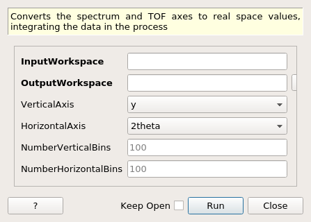
ConvertAxesToRealSpace dialog.
Table of Contents
Converts the spectrum and TOF axes to real space values, integrating the data in the process
| Name | Direction | Type | Default | Description |
|---|---|---|---|---|
| InputWorkspace | Input | MatrixWorkspace | Mandatory | An input workspace. |
| OutputWorkspace | Output | Workspace2D | An output workspace. | |
| VerticalAxis | Input | string | y | What will be the vertical axis ? Allowed values: [‘x’, ‘y’, ‘z’, ‘r’, ‘theta’, ‘phi’, ‘2theta’, ‘signed2theta’] |
| HorizontalAxis | Input | string | 2theta | What will be the horizontal axis? Allowed values: [‘x’, ‘y’, ‘z’, ‘r’, ‘theta’, ‘phi’, ‘2theta’, ‘signed2theta’] |
| NumberVerticalBins | Input | number | 100 | The number of bins along the vertical axis. |
| NumberHorizontalBins | Input | number | 100 | The number of bins along the horizontal axis. |
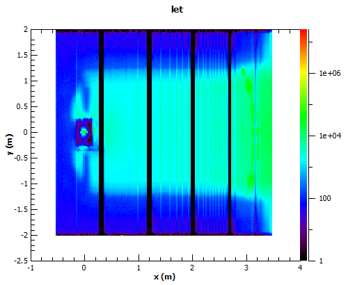
LET converted to X and Y
This converts the workspace into a 2D view of real space detector positions based on the detector positions. This is intended for rapid visualization and has been optimized for speed for use in Live data streams. If the data provided has data binned in Time of flight or any other unit this will be integrated into a single value per detector, before converting to the selected detector and rebinning to the new grid. The output grid is based in the maximum and minimum values of the detectors for axes selected, and the number of bins selected. The rebinning is simply based on centre point rebinning, and as such can be prone to moire based artefacts, however it is fast.
As the rebinning approach is simple centre point rebinning then the quality of the final plot is sensitive to the number of bins selected for each axis, too many will cause gaps between the detectors, and too few will cause overlap in certain bins.
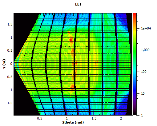
LET in 2Theta and Y
| Name | Units | Description |
|---|---|---|
| x, y ,z | meters | The absolute position of the detector as defined in the instrument definition. |
| r | meters | The absolute position of the detector in spherical coordinates, relative to 0,0,0 as defined in the instrument definition. |
| theta, phi | degrees | |
| 2theta | radians | The theta position of the detector relative to sample position and the beam direction. if the sample is at 0,0,0 and the beam direction matches, then this will match theta above. |
| signed2Theta | radians | Similar to 2theta, but with a sign calculated relative to the instrument reference frame, with the upper quadrants taking the positive value |
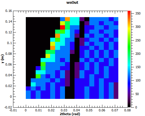
Example - ConvertAxesToRealSpace
ws = CreateSampleWorkspace(BankPixelWidth=20)
#move the 2nd bank to a better position
MoveInstrumentComponent(ws,"bank2",X=0.2,Z=-5,RelativePosition=True)

wsOut = ConvertAxesToRealSpace(ws,"y","2theta",20,20)

# Print the result
print("The output workspace has axes of {} with {} bins".format(wsOut.getAxis(1).getUnit().caption(), wsOut.getNumberHistograms()))
print("and {} with {} bins.".format(wsOut.getAxis(0).getUnit().caption(), wsOut.blocksize()))
Output:
The output workspace has axes of y with 20 bins
and 2theta with 20 bins.
Categories: AlgorithmIndex | Transforms\Units | Transforms\Axes