\(\renewcommand\AA{\unicode{x212B}}\)
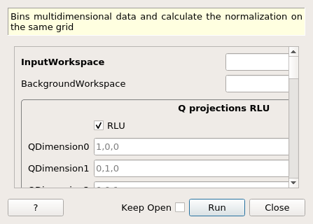
MDNorm dialog.
Table of Contents
| Name | Direction | Type | Default | Description |
|---|---|---|---|---|
| InputWorkspace | Input | MDEventWorkspace | Mandatory | An input MDEventWorkspace. Must be in Q_sample frame. |
| BackgroundWorkspace | Input | MDEventWorkspace | An (optional) input MDEventWorkspace for background. Must be in Q_lab frame. | |
| RLU | Input | boolean | True | Use reciprocal lattice units. If false, use Q_sample |
| QDimension0 | Input | dbl list | 1,0,0 | The first Q projection axis - Default is (1,0,0) |
| QDimension1 | Input | dbl list | 0,1,0 | The second Q projection axis - Default is (0,1,0) |
| QDimension2 | Input | dbl list | 0,0,1 | The thirdtCalculateCover Q projection axis - Default is (0,0,1) |
| SolidAngleWorkspace | Input | MatrixWorkspace | An input workspace containing integrated vanadium (a measure of the solid angle). Mandatory for diffraction, optional for direct geometry inelastic | |
| FluxWorkspace | Input | MatrixWorkspace | An input workspace containing momentum dependent flux. Mandatory for diffraction. No effect on direct geometry inelastic | |
| Dimension0Name | Input | string | QDimension0 | Name for the 0th dimension. Leave blank for NONE. |
| Dimension0Binning | Input | dbl list | Binning for the 0th dimension. - Leave blank for complete integration - One value is interpreted as step - Two values are interpreted integration interval - Three values are interpreted as min, step, max | |
| Dimension1Name | Input | string | QDimension1 | Name for the 1th dimension. Leave blank for NONE. |
| Dimension1Binning | Input | dbl list | Binning for the 1th dimension. - Leave blank for complete integration - One value is interpreted as step - Two values are interpreted integration interval - Three values are interpreted as min, step, max | |
| Dimension2Name | Input | string | QDimension2 | Name for the 2th dimension. Leave blank for NONE. |
| Dimension2Binning | Input | dbl list | Binning for the 2th dimension. - Leave blank for complete integration - One value is interpreted as step - Two values are interpreted integration interval - Three values are interpreted as min, step, max | |
| Dimension3Name | Input | string | Name for the 3th dimension. Leave blank for NONE. | |
| Dimension3Binning | Input | dbl list | Binning for the 3th dimension. - Leave blank for complete integration - One value is interpreted as step - Two values are interpreted integration interval - Three values are interpreted as min, step, max | |
| Dimension4Name | Input | string | Name for the 4th dimension. Leave blank for NONE. | |
| Dimension4Binning | Input | dbl list | Binning for the 4th dimension. - Leave blank for complete integration - One value is interpreted as step - Two values are interpreted integration interval - Three values are interpreted as min, step, max | |
| Dimension5Name | Input | string | Name for the 5th dimension. Leave blank for NONE. | |
| Dimension5Binning | Input | dbl list | Binning for the 5th dimension. - Leave blank for complete integration - One value is interpreted as step - Two values are interpreted integration interval - Three values are interpreted as min, step, max | |
| SymmetryOperations | Input | string | If specified the symmetry will be applied, can be space group name, point group name, or list individual symmetries. | |
| TemporaryDataWorkspace | Input | IMDHistoWorkspace | An (optional) input MDHistoWorkspace used to accumulate data from multiple MDEventWorkspaces. If unspecified a blank MDHistoWorkspace will be created. | |
| TemporaryNormalizationWorkspace | Input | IMDHistoWorkspace | An (optional) input MDHistoWorkspace used to accumulate normalization from multiple MDEventWorkspaces. If unspecified a blank MDHistoWorkspace will be created. | |
| TemporaryBackgroundDataWorkspace | Input | IMDHistoWorkspace | An (optional) input MDHistoWorkspace used to accumulate background from multiple background MDEventWorkspaces. If unspecified but BackgroundWorkspace is specified, a blank MDHistoWorkspace will be created. | |
| TemporaryBackgroundNormalizationWorkspace | Input | IMDHistoWorkspace | An (optional) input MDHistoWorkspace used to accumulate background normalization from multiple background MDEventWorkspaces. If unspecified but BackgroundWorkspace is specified, a blank MDHistoWorkspace will be created. | |
| OutputWorkspace | Output | Workspace | Mandatory | A name for the normalized output MDHistoWorkspace. |
| OutputDataWorkspace | Output | Workspace | Mandatory | A name for the output data MDHistoWorkspace. |
| OutputNormalizationWorkspace | Output | Workspace | Mandatory | A name for the output normalization MDHistoWorkspace. |
| OutputBackgroundDataWorkspace | Output | Workspace | A name for the optional output background data MDHistoWorkspace. | |
| OutputBackgroundNormalizationWorkspace | Output | Workspace | A name for the optional output background normalization MDHistoWorkspace. |
Starting from events in the momentum transfer space , this algorithm puts the data on a regular grid in either reciprocal space of the sample (if RLU is selected) or in the goniometer frame, then it normalizes to get the scattering cross section. For diffraction data, the output workspace contains the differential cross section \(\frac{d\sigma}{d\Omega}\), while for direct geometry inelastic data one obtains the double differential cross section \(\frac{d^2 \sigma}{dE d\Omega}\). One can choose any orientation for the momentum axes (to get the first axis to be [-H,H,0], set QDimension0 to -1,1,0).
Note: In order to calculate the trajectories, the algorithm relies on finding information about detector trajectories stored in the workspace. The algorithm CropWorkspaceForMDNorm must be run before converting to multidimensional workspace. Optionally, in aaddition, one can recalculate the extents of the trajectories using the RecalculateTrajectoriesExtents algorithm after convering to the multidimensional workspace.
The solid angle workspace is a MatrixWorkspace that contains the solid angle/efficiency of the detectors. One can just integrate a vanadium file between some appropriate limits. For diffraction measurements, the flux workspace is a mandatory input. It is a MatrixWorkspace that contains the indefinite integral of the incident flux. It contains one or more spectra, each of them corresponding to detectors that have the same energy response. The algorithm MDNormSCDPreprocessIncoherent can be used to process Vanadium data for the Solid Angle and Flux workspaces.
The input workspace is binned using the BinMD algorithm, to account for the selected momentum dimensions. For each dimension to be binned, we specify a name (for example Dimension0Name=’QDimension0’). For any momentum dimension the name is one of QDimension0, QDimension1, or QDimension2 along the axes specified in the algorithm. All three momentum dimensions must be present in the parameter list of the algorithm. Any other dimension name, such as DeltaE, is optional, and must be identical to a dimension in the input workspace. If a dimension name is present in the input workspace but not within the parameters of this algorithm, the corresponding data will be integrated. The semnification of binning parameters is as following:
| Format | |
|---|---|
| minimum, stepsize, maximum | The dimension in the output workspace will extend from ‘minimum’ to ‘maximum’ with bins of width ‘stepsize’. |
| minimum, maximum | A single bin will be created between ‘minimum’ and ‘maximum’. |
| stepsize | The ‘minimum’ and ‘maximum’ are set to the dimension limits; the workspace is not cut in this dimension. |
The binned workspace is stored in the OutputDataWorkspace.
Trajectories of each detector in reciprocal space are omputed, and the normalization is calculated between intersections with each MDBox. A brief introduction to the multi-dimensional data normalization can be found here. The OutputNormalizationWorkspace contains the denominator of equations (2) or (3). In the normalization document.
The OutputWorkspace contains the ratio of the OutputDataWorkspace and OutputNormalizationWorkspace.
One can accumulate multiple inputs. The correct way to do it is to add the counts together, add the normalizations together, then divide. For user convenience, one can provide these accumulation workspaces as TemporaryDataWorkspace and TemporaryNormalizationWorkspace.
There are symmetrization options for the data. To achieve this option, one can use the SymmetryOperations parameter. It can accept a space group name, a point group name, or a list of symmetry operations. More information about symmetry operations can be found here and here
Starting with Mantid 6.1, the algorithm allows efficient processing of the background. In previous versions one used to create a background MD Event workspaces by replicating data for each goniometer setting in the input workspace. The current implementation uses instead an MD Event workspace in the sample frame of the laboratory, so no need to replicate the background data.
Similar to the case without background, temporary histogram workspaces are created for the background data and background normalization. The output is given by:
Example - MDNorm
For diffraction measurements a sample code is found below:
Load(Filename='CORELLI_29782.nxs', OutputWorkspace='data')
Load(Filename='SingleCrystalDiffuseReduction_SA.nxs', OutputWorkspace='SolidAngle')
Load(Filename='SingleCrystalDiffuseReduction_Flux.nxs', OutputWorkspace= 'Flux')
MaskDetectors(Workspace='data', MaskedWorkspace='SolidAngle')
ConvertUnits(InputWorkspace='data',OutputWorkspace='data',Target='Momentum')
CropWorkspaceForMDNorm(InputWorkspace='data',
XMin=2.5,
XMax=10,
OutputWorkspace='data')
LoadIsawUB(InputWorkspace='data',Filename='SingleCrystalDiffuseReduction_UB.mat')
SetGoniometer(Workspace='data',Axis0='BL9:Mot:Sample:Axis1,0,1,0,1')
min_vals,max_vals=ConvertToMDMinMaxGlobal(InputWorkspace='data',
QDimensions='Q3D',
dEAnalysisMode='Elastic',
Q3DFrames='Q')
ConvertToMD(InputWorkspace='data',
QDimensions='Q3D',
dEAnalysisMode='Elastic',
Q3DFrames='Q_sample',
OutputWorkspace='md',
MinValues=min_vals,
MaxValues=max_vals)
RecalculateTrajectoriesExtents(InputWorkspace= 'md', OutputWorkspace='md')
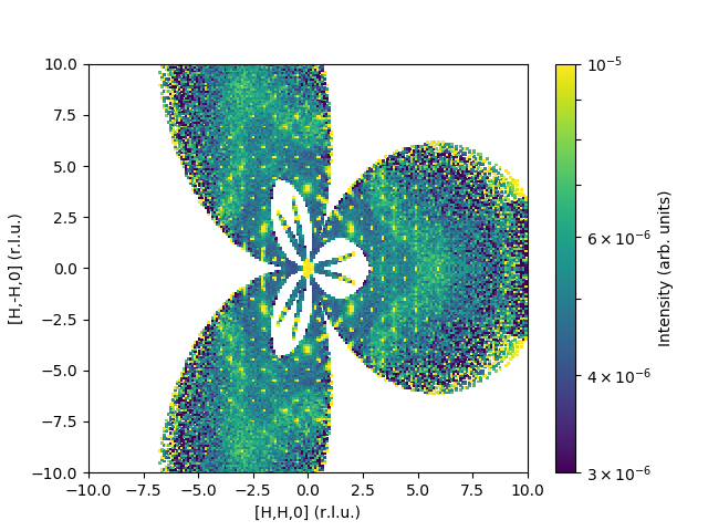
MDNorm(InputWorkspace='md',
SolidAngleWorkspace='SolidAngle',
FluxWorkspace='Flux',
QDimension0='1,1,0',
QDimension1='1,-1,0',
QDimension2='0,0,1',
Dimension0Name='QDimension0',
Dimension0Binning='-10.0,0.1,10.0',
Dimension1Name='QDimension1',
Dimension1Binning='-10.0,0.1,10.0',
Dimension2Name='QDimension2',
Dimension2Binning='-0.1,0.1',
SymmetryOperations='P 31 2 1',
OutputWorkspace='result',
OutputDataWorkspace='dataMD',
OutputNormalizationWorkspace='normMD')
The output would look like:
Here is a sample code for inelastic data:
Load(Filename='HYS_13656-13658',OutputWorkspace='sum')
SetGoniometer(Workspace='sum', Axis0='s1,0,1,0,1')
GenerateEventsFilter(InputWorkspace='sum',
OutputWorkspace='splboth',
InformationWorkspace='info',
UnitOfTime='Nanoseconds',
LogName='s1',
MaximumLogValue=90,
LogValueInterval=1)
FilterEvents(InputWorkspace='sum',
SplitterWorkspace='splboth',
InformationWorkspace='info',
FilterByPulseTime=True,
GroupWorkspaces=True,
OutputWorkspaceIndexedFrom1=True,
OutputWorkspaceBaseName='split')
DgsReduction(SampleInputWorkspace='split',
SampleInputMonitorWorkspace='split_1',
IncidentEnergyGuess=50,
SofPhiEIsDistribution=False,
TimeIndepBackgroundSub=True,
TibTofRangeStart=10400,
TibTofRangeEnd=12400,
OutputWorkspace='reduced')
SetUB(Workspace='reduced',
a=5.823,
b=6.475,
c=3.186,
u='0,1,0',
v='0,0,1')
CropWorkspaceForMDNorm(InputWorkspace='reduced',
XMin=-25,
XMax=49,
OutputWorkspace='reduced')
ConvertToMD(InputWorkspace='reduced',
QDimensions='Q3D',
Q3DFrames='Q_sample',
OutputWorkspace='md',
MinValues='-11,-11,-11,-25',
MaxValues='11,11,11,49')
MergeMD(InputWorkspaces='md', OutputWorkspace='merged')
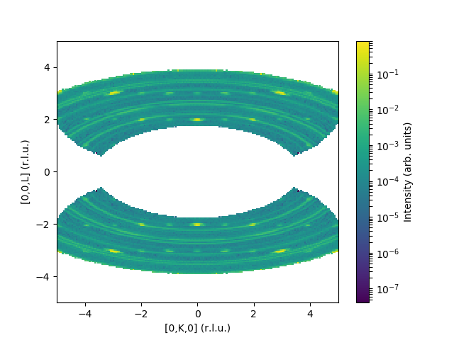
MDNorm(InputWorkspace='merged',
Dimension0Name='QDimension1',
Dimension0Binning='-5,0.05,5',
Dimension1Name='QDimension2',
Dimension1Binning='-5,0.05,5',
Dimension2Name='DeltaE',
Dimension2Binning='-2,2',
Dimension3Name='QDimension0',
Dimension3Binning='-0.5,0.5',
SymmetryOperations='x,y,z;x,-y,z;x,y,-z;x,-y,-z',
OutputWorkspace='result',
OutputDataWorkspace='dataMD',
OutputNormalizationWorkspace='normMD')
and the corresponding output:
To subtract background one must create the background workspace in \(Q_{lab}\) frame. For example, in the previous script one can use reduced_3 workspace as a background. Add the following lines
ConvertToMD(InputWorkspace='reduced_3',
            QDimensions='Q3D',
            dEAnalysisMode='Direct',
            Q3DFrames="Q_lab",
            MinValues='-11,-11,-11,-25',
            MaxValues='11,11,11,49',
            PreprocDetectorsWS='-',
            OutputWorkspace='background_MDE_lab')

MDNorm(InputWorkspace='merged',
       BackgroundWorkspace='background_MDE_lab',
       Dimension0Name='QDimension1',
       Dimension0Binning='-5,0.05,5',
       Dimension1Name='QDimension2',
       Dimension1Binning='-5,0.05,5',
       Dimension2Name='DeltaE',
       Dimension2Binning='-2,2',
       Dimension3Name='QDimension0',
       Dimension3Binning='-0.5,0.5',
       SymmetryOperations='x,y,z;x,-y,z;x,y,-z;x,-y,-z',
       OutputWorkspace='result',
       OutputDataWorkspace='dataMD',
       OutputNormalizationWorkspace='normMD',
       OutputBackgroundDataWorkspace='bkgDataMD',
       OutputBackgroundNormalizationWorkspace='bkgNormMD')
Not always can data be processed in one chunk. We sometimes just want to add a few more files to a final image. In the previous script, let’s assume that the first 30 MDEvent workspaces correspond to data processed in chunk 1, and the remaining workspaces correspond to chunk 2. The output histograms for data, normalization, background data, and background normalization when running the algorithm on the first chunk will be used as temporary workspaces for the second chunk:
MergeMD(InputWorkspaces=','.join([f'md_{i}' for i in range(1,30)]) , OutputWorkspace='merged_1')

MDNorm(InputWorkspace='merged_1',
       BackgroundWorkspace='background_MDE_lab',
       Dimension0Name='QDimension1',
       Dimension0Binning='-5,0.05,5',
       Dimension1Name='QDimension2',
       Dimension1Binning='-5,0.05,5',
       Dimension2Name='DeltaE',
       Dimension2Binning='-2,2',
       Dimension3Name='QDimension0',
       Dimension3Binning='-0.5,0.5',
       SymmetryOperations='x,y,z;x,-y,z;x,y,-z;x,-y,-z',
       OutputWorkspace='result_1',
       OutputDataWorkspace='dataMD_1',
       OutputNormalizationWorkspace='normMD_1',
       OutputBackgroundDataWorkspace='bkgData_1',
       OutputBackgroundNormalizationWorkspace='bkgNorm_1')

MergeMD(InputWorkspaces=','.join([f'md_{i}' for i in range(30,93)]) , OutputWorkspace='merged_2')
MDNorm(InputWorkspace='merged_2',
       BackgroundWorkspace='background_MDE_lab',
       Dimension0Name='QDimension1',
       Dimension0Binning='-5,0.05,5',
       Dimension1Name='QDimension2',
       Dimension1Binning='-5,0.05,5',
       Dimension2Name='DeltaE',
       Dimension2Binning='-2,2',
       Dimension3Name='QDimension0',
       Dimension3Binning='-0.5,0.5',
       SymmetryOperations='x,y,z;x,-y,z;x,y,-z;x,-y,-z',
       TemporaryDataWorkspace='dataMD_1',
       TemporaryNormalizationWorkspace='normMD_1',
       TemporaryBackgroundDataWorkspace='bkgData_1',
       TemporaryBackgroundNormalizationWorkspace='bkgNorm_1',
       OutputWorkspace='result_2',
       OutputDataWorkspace='dataMD_2',
       OutputNormalizationWorkspace='normMD_2',
       OutputBackgroundDataWorkspace='bkgData_2',
       OutputBackgroundNormalizationWorkspace='bkgNorm2')
Note that the output workspaces after the second call to the algorithm will contain procesed information from both chunks.
Categories: AlgorithmIndex | MDAlgorithms\Normalisation