\(\renewcommand\AA{\unicode{x212B}}\)
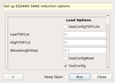
SetupEQSANSReduction dialog.
Table of Contents
| Name | Direction | Type | Default | Description |
|---|---|---|---|---|
| UseConfigTOFCuts | Input | boolean | False | If true, the edges of the TOF distribution will be cut according to the configuration file |
| LowTOFCut | Input | number | 0 | TOF value below which events will not be loaded into the workspace at load-time |
| HighTOFCut | Input | number | 0 | TOF value above which events will not be loaded into the workspace at load-time |
| WavelengthStep | Input | number | 0.1 | Wavelength steps to be used when rebinning the data before performing the reduction |
| UseConfigMask | Input | boolean | False | If true, the masking information found in the configuration file will be used |
| UseConfig | Input | boolean | True | If true, the best configuration file found will be used |
| CorrectForFlightPath | Input | boolean | False | If true, the TOF will be modified for the true flight path from the sample to the detector pixel |
| SkipTOFCorrection | Input | boolean | False | If true, the EQSANS TOF correction will be skipped |
| PreserveEvents | Input | boolean | False | If true, the output workspace will be an event workspace |
| SampleDetectorDistance | Input | number | Optional | Sample to detector distance to use (overrides meta data), in mm |
| SampleDetectorDistanceOffset | Input | number | Optional | Offset to the sample to detector distance (use only when using the detector distance found in the meta data), in mm |
| SampleOffset | Input | number | Optional | Offset applies to the sample position (use only when using the detector distance found in the meta data), in mm |
| DetectorOffset | Input | number | Optional | Offset applies to the detector position (use only when using the distance found in the meta data), in mm |
| SolidAngleCorrection | Input | boolean | True | If true, the solid angle correction will be applied to the data |
| DetectorTubes | Input | boolean | False | If true, the solid angle correction for tube detectors will be applied |
| LoadNexusInstrumentXML | Input | boolean | True | Reads the embedded Instrument XML from the NeXus file (optional, default True). |
| BeamCenterMethod | Input | string | None | Method for determining the data beam center. Allowed values: [‘None’, ‘Value’, ‘DirectBeam’, ‘Scattering’] |
| UseConfigBeam | Input | boolean | False | If True, the beam center will be taken from the config file |
| BeamCenterX | Input | number | Optional | Position of the beam center, in pixel |
| BeamCenterY | Input | number | Optional | Position of the beam center, in pixel |
| BeamCenterFile | Input | string | The name of the input event Nexus file to load. Allowed extensions: [‘_event.nxs’] | |
| BeamRadius | Input | number | Optional | Radius of the beam area used the exclude the beam when calculating the center of mass of the scattering pattern [pixels]. Default=3.0 |
| Normalisation | Input | string | BeamProfileAndCharge | Options for data normalisation. Allowed values: [‘None’, ‘Monitor’, ‘BeamProfileAndCharge’, ‘Charge’] |
| LoadMonitors | Input | boolean | False | If true, the monitor workspace will be loaded |
| MonitorReferenceFile | Input | string | The name of the beam monitor reference file used for normalisation. Allowed extensions: [‘_event.nxs’] | |
| DarkCurrentFile | Input | string | The name of the input event Nexus file to load as dark current. Allowed extensions: [‘_event.nxs’] | |
| SensitivityFile | Input | string | Flood field or sensitivity file. Allowed extensions: [‘_event.nxs’] | |
| MinEfficiency | Input | number | Optional | Minimum efficiency for a pixel to be considered (default: no minimum). |
| MaxEfficiency | Input | number | Optional | Maximum efficiency for a pixel to be considered (default: no maximum). |
| UseDefaultDC | Input | boolean | True | If true, the dark current subtracted from the sample data will also be subtracted from the flood field. |
| SensitivityDarkCurrentFile | Input | string | The name of the input file to load as dark current. Allowed extensions: [‘_event.nxs’] | |
| SensitivityBeamCenterMethod | Input | string | None | Method for determining the sensitivity data beam center. Allowed values: [‘None’, ‘Value’, ‘DirectBeam’, ‘Scattering’] |
| SensitivityBeamCenterX | Input | number | Optional | Sensitivity beam center location in X [pixels] |
| SensitivityBeamCenterY | Input | number | Optional | Sensitivity beam center location in Y [pixels] |
| SensitivityBeamCenterFile | Input | string | The name of the input data file to load. Allowed extensions: [‘.xml’] | |
| SensitivityBeamCenterRadius | Input | number | Optional | Radius of the beam area used the exclude the beam when calculating the center of mass of the scattering pattern [pixels]. Default=3.0 |
| OutputSensitivityWorkspace | Input | string | Name to give the sensitivity workspace | |
| TransmissionMethod | Input | string | Value | Transmission determination method. Allowed values: [‘Value’, ‘DirectBeam’] |
| TransmissionValue | Input | number | Optional | Transmission value. |
| TransmissionError | Input | number | Optional | Transmission error. |
| TransmissionBeamRadius | Input | number | 3 | Radius of the beam area used to compute the transmission [pixels] |
| TransmissionSampleDataFile | Input | string | Sample data file for transmission calculation. Allowed extensions: [‘.xml’] | |
| TransmissionEmptyDataFile | Input | string | Empty data file for transmission calculation. Allowed extensions: [‘.xml’] | |
| FitFramesTogether | Input | boolean | False | If true, the two frames will be fit together |
| TransmissionBeamCenterMethod | Input | string | None | Method for determining the transmission data beam center. Allowed values: [‘None’, ‘Value’, ‘DirectBeam’, ‘Scattering’] |
| TransmissionBeamCenterX | Input | number | Optional | Transmission beam center location in X [pixels] |
| TransmissionBeamCenterY | Input | number | Optional | Transmission beam center location in Y [pixels] |
| TransmissionBeamCenterFile | Input | string | The name of the input data file to load. Allowed extensions: [‘.xml’] | |
| TransmissionDarkCurrentFile | Input | string | The name of the input data file to load as transmission dark current. Allowed extensions: [‘.xml’] | |
| TransmissionUseSampleDC | Input | boolean | True | If true, the sample dark current will be used IF a dark current file isnot set. |
| ThetaDependentTransmission | Input | boolean | True | If true, a theta-dependent transmission correction will be applied. |
| BackgroundFiles | Input | string | Background data files | |
| BckTransmissionMethod | Input | string | Value | Transmission determination method. Allowed values: [‘Value’, ‘DirectBeam’] |
| BckTransmissionValue | Input | number | Optional | Transmission value. |
| BckTransmissionError | Input | number | Optional | Transmission error. |
| BckTransmissionBeamRadius | Input | number | 3 | Radius of the beam area used to compute the transmission [pixels] |
| BckTransmissionSampleDataFile | Input | string | Sample data file for transmission calculation. Allowed extensions: [‘.xml’] | |
| BckTransmissionEmptyDataFile | Input | string | Empty data file for transmission calculation. Allowed extensions: [‘.xml’] | |
| BckFitFramesTogether | Input | boolean | False | If true, the two frames will be fit together |
| BckTransmissionBeamCenterMethod | Input | string | None | Method for determining the transmission data beam center. Allowed values: [‘None’, ‘Value’, ‘DirectBeam’, ‘Scattering’] |
| BckTransmissionBeamCenterX | Input | number | Optional | Transmission beam center location in X [pixels] |
| BckTransmissionBeamCenterY | Input | number | Optional | Transmission beam center location in Y [pixels] |
| BckTransmissionBeamCenterFile | Input | string | The name of the input data file to load. Allowed extensions: [‘.xml’] | |
| BckTransmissionDarkCurrentFile | Input | string | The name of the input data file to load as background transmission dark current. Allowed extensions: [‘.xml’] | |
| BckThetaDependentTransmission | Input | boolean | True | If true, a theta-dependent transmission correction will be applied. |
| SampleThickness | Input | number | Optional | Sample thickness [cm] |
| MaskedDetectorList | Input | int list | List of detector IDs to be masked | |
| MaskedEdges | Input | int list | Number of pixels to mask on the edges: X-low, X-high, Y-low, Y-high | |
| MaskedSide | Input | string | None | Mask one side of the detector. Allowed values: [‘None’, ‘Front’, ‘Back’] |
| AbsoluteScaleMethod | Input | string | None | Absolute scale correction method. Allowed values: [‘None’, ‘Value’, ‘ReferenceData’] |
| AbsoluteScalingFactor | Input | number | 1 | Absolute scaling factor |
| AbsoluteScalingReferenceFilename | Input | string | Allowed extensions: [‘.xml’] | |
| AbsoluteScalingBeamDiameter | Input | number | 0 | Beamstop diameter for computing the absolute scale factor [mm]. Read from file if not supplied. |
| AbsoluteScalingAttenuatorTrans | Input | number | 1 | Attenuator transmission value for computing the absolute scale factor |
| AbsoluteScalingApplySensitivity | Input | boolean | False | Apply sensitivity correction to the reference data when computing the absolute scale factor |
| DoAzimuthalAverage | Input | boolean | True | |
| IQNumberOfBins | Input | number | 100 | Number of I(q) bins when binning is not specified |
| IQLogBinning | Input | boolean | False | I(q) log binning when binning is not specified |
| IQIndependentBinning | Input | boolean | True | If true and frame skipping is used, each frame will have its own binning |
| IQScaleResults | Input | boolean | True | If true and frame skipping is used, frame 1 will be scaled to frame 2 |
| ComputeResolution | Input | boolean | False | If true the Q resolution will be computed |
| SampleApertureDiameter | Input | number | 10 | Sample aperture diameter [mm] |
| Do2DReduction | Input | boolean | True | |
| IQ2DNumberOfBins | Input | number | 100 | Number of I(qx,qy) bins. |
| ProcessInfo | Input | string | Additional process information | |
| OutputDirectory | Input | string | Directory to put the output files in | |
| OutputMessage | Output | string | ||
| ReductionProperties | Input | string | __sans_reduction_properties |
Create a PropertyManager object setting the reduction options for EQSANS. The property manager object is then added to the PropertyManagerDataService.
See SANSReduction for details.
Categories: AlgorithmIndex | Workflow\SANS