\(\renewcommand\AA{\unicode{x212B}}\)
PDCalibration v1
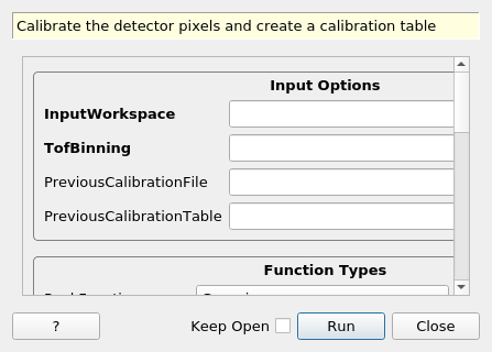
PDCalibration dialog.
Summary
Calibrate the detector pixels and create a calibration table
Properties
Name |
Direction |
Type |
Default |
Description |
|---|---|---|---|---|
InputWorkspace |
InOut |
Mandatory |
Input signal workspace |
|
TofBinning |
Input |
dbl list |
Mandatory |
Min, Step, and Max of time-of-flight bins. Logarithmic binning is used if Step is negative. |
PreviousCalibrationFile |
Input |
string |
Previous calibration file. Allowed extensions: [‘.h5’, ‘.cal’] |
|
PreviousCalibrationTable |
Input |
Previous calibration table. This overrides results from previous file. |
||
PeakFunction |
Input |
string |
Gaussian |
Allowed values: [‘BackToBackExponential’, ‘Gaussian’, ‘Lorentzian’, ‘PseudoVoigt’, ‘IkedaCarpenterPV’] |
BackgroundType |
Input |
string |
Linear |
Type of Background. Allowed values: [‘Flat’, ‘Linear’, ‘Quadratic’] |
PeakPositions |
Input |
dbl list |
Mandatory |
Comma delimited d-space positions of reference peaks. |
PeakWindow |
Input |
dbl list |
0.1 |
Window over which to fit a peak in d-spacing (if a single value is supplied it will used as half the window width for all peaks, otherwise a comma delimited list of boundaries). |
PeakWidthPercent |
Input |
number |
Optional |
The estimated peak width as a percent of the peakcenter value, in d-spacing or TOF units. |
MinimumPeakHeight |
Input |
number |
2 |
Minimum peak height such that all the fitted peaks with height under this value will be excluded. |
MaxChiSq |
Input |
number |
100 |
Maximum chisq value for individual peak fit allowed. (Default: 100) |
ConstrainPeakPositions |
Input |
boolean |
False |
If true, peak centers will be constrained by estimated positions (highest Y value position) and the peak width will either be estimated by observation or calculated. |
CalibrationParameters |
Input |
string |
DIFC |
Select calibration parameters to fit. Allowed values: [‘DIFC’, ‘DIFC+TZERO’, ‘DIFC+TZERO+DIFA’] |
TZEROrange |
Input |
dbl list |
Range for allowable TZERO from calibration (default is all) |
|
DIFArange |
Input |
dbl list |
Range for allowable DIFA from calibration (default is all) |
|
UseChiSq |
Input |
boolean |
False |
By default the square of the peak height is used as weights in the least-squares fit to find the diffractometer constants, if UseChiSq is true then the inverse square of the error on the fitted peak centres will be used instead. |
OutputCalibrationTable |
Output |
Mandatory |
Output table workspace containing the calibration |
|
DiagnosticWorkspaces |
Output |
WorkspaceGroup |
Mandatory |
Workspaces to promote understanding of calibration results |
Description
This algorithm calibrates the detector pixels and creates a
diffraction calibration workspace. Unlike
CalibrateRectangularDetectors the peak fitting and
calibration is done in TOF not d spacing. The peak d values are
converted to TOF based on either the old calibration or the instrument
geometry. The InputWorkspace contains the data from a standard
sample. The results are then fitted with up to (in order) difc,
t_zero, and difa. These values are described in detail
in AlignDetectors v1.
The peak fitting properties are explained in more detail in FitPeaks v1. This is used to perform a refinement of peaks using as much information as is provided as possible. Each input spectrum is calibrated separately following the same basic steps:
The
PeakPositionsare used to determine fit windows in combination withPeakWindow. The windows are half the distance between the provided peak positions, with a maximum size ofPeakWindow.The positions and windows are converted to time-of-flight for the spectrum using either the previous calibration information or the spectrum’s geometry.
For each peak, the background is estimated from the first and last ten points in the fit window.
For each peak, the nominal center is selected by locating the highest point near the expected position. The height is used as the initial guess as well.
For each peak, the width is estimated by multiplying the peak center position with
PeakWidthPercentor by calculating the second moment of the data in the window.For each peak, the peak fit parameters are refined.
All of the fitted peak centers are used to fit the calibration constants, weighted by peak height.
If more than one constant is requested, the result that has the lowest reduced chi-squared value is returned. This favors using less parameters.
A mask workspace is created, named “OutputCalibrationTable” + ‘_mask’, with uncalibrated pixels masked.
The resulting calibration table can be saved with
SaveDiffCal v1, loaded with LoadDiffCal v1 and
applied to a workspace with AlignDetectors v1. There are also
three workspaces placed in the DiagnosticWorkspace group. They are:
evaluated fit functions (
_fitted)raw peak fit values (
_fitparam)contain the fitted positions in dspace(
_dspacing)peak widths (
_width)peak heights (
_height)instrument resolution (delta-d/d
_resolution)
Since multiple peak shapes can be used,
see the documentation for the individual fit functions to see how they relate to the effective
values displayed in the diagnostic tables. For Gaussian and
Lorentzian, the widths and resolution are converted to values that
can be directly compared with the results of
EstimateResolutionDiffraction v1.
Usage
Example - PDCalibration
# If you have an old calibration it can be used as the starting point
oldCal = 'NOM_calibrate_d72460_2016_05_23.h5'

# list of d values for diamond
dvalues = (0.3117,0.3257,0.3499,0.4205,0.4645,0.4768,0.4996,0.5150,0.5441,0.5642,0.5947,0.6307,.6866,.7283,.8185,.8920,1.0758,1.2615,2.0599)

LoadEventNexus(Filename='NOM_72460', OutputWorkspace='NOM_72460')
PDCalibration(InputWorkspace='NOM_72460',
              TofBinning=[300,-.001,16666.7],
              PreviousCalibrationFile=oldCal,
              PeakPositions=dvalues,
              PeakWidthPercent=.008,
              OutputCalibrationTable='cal',
              DiagnosticWorkspaces='diag')

# Print the result
print("The calibrated difc at detid {detid} is {difc}".format(**mtd['cal'].row(40000)))
Output:
The calibrated difc at detid 40896 is 5523.060327692842
Example - PDCalibration with BackToBackExponential fit function
The following example shows how to use PDCalibration with the BackToBackExponential fit function. The fit works best if sensible initial values for the parameters are specified in an instrument definition or parameter file (for more details, see the fitting parameters documentation):
Load(Filename=r'ENGINX00193749.nxs', OutputWorkspace='193749')
dpks = (1.913220892, 1.631600313,
        1.562138267, 1.352851554, 1.104598643)

# initial values for GSAS parameters A, B, S are in ENGINX parameters .xml
# use log binning
PDCalibration(InputWorkspace='193749',
              TofBinning=[10000,-0.0005,46000],
              PeakPositions=dpks,
              PeakWindow = 0.03,
              MinimumPeakHeight = 0.5,
              PeakFunction = 'BackToBackExponential',
              CalibrationParameters = 'DIFC',
              OutputCalibrationTable='cal_B2B_DIFC_chisqTrue',
              DiagnosticWorkspaces = 'diag_B2B_DIFC_chisqTrue',
              UseChiSq = True)

# Print the result
print("The calibrated difc at detid {detid} is {difc}".format(**mtd['cal_B2B_DIFC_chisqTrue'].row(1000)))
Output:
The calibrated difc at detid 108041 is 16834.952770921267
Categories: AlgorithmIndex | Diffraction\Calibration
Source
C++ header: PDCalibration.h
C++ source: PDCalibration.cpp