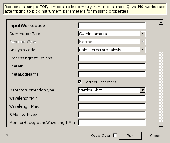
ReflectometryReductionOneAuto dialog.
Table of Contents
Reduces a single TOF/Lambda reflectometry run into a mod Q vs I/I0 workspace attempting to pick instrument parameters for missing properties
| Name | Direction | Type | Default | Description |
|---|---|---|---|---|
| InputWorkspace | Input | MatrixWorkspace | Mandatory | Input run in TOF or wavelength |
| SummationType | Input | string | SumInLambda | The type of summation to perform. Allowed values: [‘SumInLambda’, ‘SumInQ’] |
| ReductionType | Input | string | Normal | The type of reduction to perform when summing in Q. Allowed values: [‘Normal’, ‘DivergentBeam’, ‘NonFlatSample’] |
| AnalysisMode | Input | string | PointDetectorAnalysis | Analysis mode. This property is only used when ProcessingInstructions is not set. Allowed values: [‘PointDetectorAnalysis’, ‘MultiDetectorAnalysis’] |
| ProcessingInstructions | Input | string | Grouping pattern of workspace indices to yield only the detectors of interest. See GroupDetectors for syntax. | |
| ThetaIn | Input | number | Optional | Angle in degrees |
| ThetaLogName | Input | string | The name ThetaIn can be found in the run log as | |
| CorrectDetectors | Input | boolean | True | Moves detectors to twoTheta if ThetaIn or ThetaLogName is given |
| DetectorCorrectionType | Input | string | VerticalShift | When correcting detector positions, this determines whether detectorsshould be shifted vertically or rotated around the sample position. Allowed values: [‘RotateAroundSample’, ‘VerticalShift’] |
| WavelengthMin | Input | number | Optional | Wavelength Min in angstroms |
| WavelengthMax | Input | number | Optional | Wavelength Max in angstroms |
| I0MonitorIndex | Input | number | Optional | I0 monitor workspace index |
| MonitorBackgroundWavelengthMin | Input | number | Optional | Wavelength minimum for monitor background subtraction in angstroms. |
| MonitorBackgroundWavelengthMax | Input | number | Optional | Wavelength maximum for monitor background subtraction in angstroms. |
| MonitorIntegrationWavelengthMin | Input | number | Optional | Wavelength minimum for integration in angstroms. |
| MonitorIntegrationWavelengthMax | Input | number | Optional | Wavelength maximum for integration in angstroms. |
| NormalizeByIntegratedMonitors | Input | boolean | True | Normalize by dividing by the integrated monitors. |
| FirstTransmissionRun | Input | MatrixWorkspace | First transmission run, or the low wavelength transmission run if SecondTransmissionRun is also provided. | |
| SecondTransmissionRun | Input | MatrixWorkspace | Second, high wavelength transmission run. Optional. Causes the FirstTransmissionRun to be treated as the low wavelength transmission run. | |
| Params | Input | dbl list | A comma separated list of first bin boundary, width, last bin boundary. These parameters are used for stitching together transmission runs. Values are in wavelength (angstroms). This input is only needed if a SecondTransmission run is provided. | |
| StartOverlap | Input | number | Optional | Start wavelength for stitching transmission runs together. Only used if a second transmission run is provided. |
| EndOverlap | Input | number | Optional | End wavelength (angstroms) for stitching transmission runs together. Only used if a second transmission run is provided. |
| StrictSpectrumChecking | Input | boolean | True | Enforces spectrum number checking prior to normalization by transmission workspace. Applies to input workspace and transmission workspace. |
| CorrectionAlgorithm | Input | string | AutoDetect | The type of correction to perform. Allowed values: [‘None’, ‘AutoDetect’, ‘PolynomialCorrection’, ‘ExponentialCorrection’] |
| Polynomial | Input | dbl list | Coefficients to be passed to the PolynomialCorrection algorithm. | |
| C0 | Input | number | 0 | C0 value to be passed to the ExponentialCorrection algorithm. |
| C1 | Input | number | 0 | C1 value to be passed to the ExponentialCorrection algorithm. |
| MomentumTransferMin | Input | number | Optional | Minimum Q value in IvsQ Workspace. Used for Rebinning the IvsQ Workspace |
| MomentumTransferStep | Input | number | Optional | Resolution value in IvsQ Workspace. Used for Rebinning the IvsQ Workspace. This value will be made minus to apply logarithmic rebinning. If you wish to have linear bin-widths then please provide a negative value. |
| MomentumTransferMax | Input | number | Optional | Maximum Q value in IvsQ Workspace. Used for Rebinning the IvsQ Workspace |
| ScaleFactor | Input | number | Optional | Factor you wish to scale Q workspace by. |
| PolarizationAnalysis | Input | string | None | Polarization analysis mode. Allowed values: [‘None’, ‘PA’, ‘PNR’] |
| CPp | Input | dbl list | Effective polarizing power of the polarizing system. Expressed as a ratio 0 < Pp < 1 | |
| CAp | Input | dbl list | Effective polarizing power of the analyzing system. Expressed as a ratio 0 < Ap < 1 | |
| CRho | Input | dbl list | Ratio of efficiencies of polarizer spin-down to polarizer spin-up. This is characteristic of the polarizer flipper. Values are constants for each term in a polynomial expression. | |
| CAlpha | Input | dbl list | Ratio of efficiencies of analyzer spin-down to analyzer spin-up. This is characteristic of the analyzer flipper. Values are factors for each term in a polynomial expression. | |
| Diagnostics | Input | boolean | False | Whether to enable the output of interim workspaces for debugging purposes. |
| OutputWorkspaceBinned | Output | MatrixWorkspace | Mandatory | Output workspace in Q (rebinned workspace) |
| OutputWorkspace | Output | MatrixWorkspace | Mandatory | Output workspace in Q (native binning) |
| OutputWorkspaceWavelength | Output | MatrixWorkspace | Mandatory | Output workspace in wavelength |
This algorithm is a facade over ReflectometryReductionOne v2 (see ReflectometryReductionOne v2 for more information on the wrapped algorithm). It optionally corrects the detector position and then pulls numeric parameters out of the instrument parameter file where possible. These automatically applied defaults can be overriden by providing your own values. In addition, it outputs a rebinned workspace in Q, and it optionally performs polarization analysis if the input workspace is a workspace group.
First, if ThetaIn is given the algorithm will try to correct the detector position. For this, it uses ProcessingInstructions, which corresponds to the grouping pattern of workspace indices that define the detectors of interest. Only the detectors of interest will be corrected, the rest of the instrument components will remain in the original position. Note that when ProcessingInstructions is not set, its value is inferred from other properties, depending on the value of AnalysisMode:
Note that ProcessingInstructions are workspace indices, not detector IDs. The first few workspaces may correspond to monitors, rather than detectors of interest. For the syntax of this property, see GroupDetectors v2.
theta is calcualted using SpecularReflectionCalculateTheta. This is passed through to ReflectometryReductionOne and 2 * theta is passed through to CalculateResolution. theta can be overridden by setting ThetaIn or ThetaLogName (ThetaIn takes precedence if both are given). If CorrectDetectors is also true, then the algorithm corrects the positions of the detectors of interest to 2 * theta using SpecularReflectionPositionCorrect v2. The detectors are moved either by shifting them vertically, or by rotating them around the sample position, as specified by DetectorCorrectionType.
Next, the algorithm will try to populate input properties which have not been set. Specifically, it will search for LambdaMin, LambdaMax, I0MonitorIndex, MonitorBackgroundMin, MonitorBackgroundMax, MonitorIntegralMin and MonitorIntegralMin in the parameter file to populate WavelengthMin, WavelengthMax, I0MonitorIndex, MonitorBackgroundWavelengthMin, MonitorBackgroundWavelengthMax, MonitorIntegrationWavelengthMin and MonitorIntegrationWavelengthMax respectively. The first two properties will be used by ReflectometryReductionOne v2 to crop the workspace in wavelength, whereas the rest of the properties refer to monitors and are used to create a temporary monitor workspace by which the detectors of interest will be normalized. Note that there is an additional property referring to monitors, NormalizeByIntegratedMonitors, which can be used to specify whether or not integrated monitors should be considered.
The rest of the input properties are not inferred from the parameter file, and must be specified manually. RegionOfDirectBeam is an optional property that allows users to specify a region of direct beam that will be used to normalize the detector signal. The region of direct beam is specified by workspace indices. For instance, RegionOfDirectBeam='2-3' means that spectra with workspace indices 2 and 3 will be summed and the resulting workspace will be used as the direct beam workspace.
Transmission corrections can be optionally applied by providing either one or two transmission runs or polynomial corrections. Polynomial correction is enabled by setting the CorrectionAlgorithm property. If set to AutoDetect, the algorithm looks at the instrument parameters for the correction parameter. If this parameter is set to polynomial, then polynomial correction is performed using the PolynomialCorrection v1 algorithm, with the polynomial string taken from the instrument’s polystring parameter. If the correction parameter is set to exponential instead, then the ExponentialCorrection v1 algorithm is used, with C0 and C1 taken from the instrument parameters, C0 and C1. All these values can be specified manually by setting the CorrectionAlgorithm to either PolynomialCorrection or ExponentialCorrection and setting Polynomial or C0 and C1 properties accordingly. Note that when using a correction algorithm, monitors will not be integrated, even if NormalizeByIntegratedMonitors was set to true.
Finally, properties MomentumTransferMin, MomentumTransferStep and MomentumTransferMax are used to rebin the output workspace in Q, and ScaleFactor is used to scale the rebinned workspace. When they are not provided the algorithm will attempt to determine the bin width using NRCalculateSlitResolution v1 (note that, for the latter to run successfully, a slit component with a vertical gap must be defined in the instrument definition file).
See ReflectometryReductionOne v2 for more information on how the input properties are used by the wrapped algorithm.
If a workspace group is provided as input, each workspace in the group will be reduced independently and sequentially using ReflectometryReductionOne v2. Each of these individual reductions will produce three output workspaces: an output workspace in wavelength, an output workspace in Q with native binning, and a rebinned workspace in Q. Output workspaces in wavelength will be grouped together to produce an output workspace group in wavelength, and output workspaces in Q will be grouped together to produce an output workspace group in Q. The diagram below illustrates this process (note that, for the sake of clarity, the rebinned output workspace in Q, OutputWorkspaceBinned, is not represented but it is handled analogously to OutputWorkspace and OutputWorkspaceWavelength):
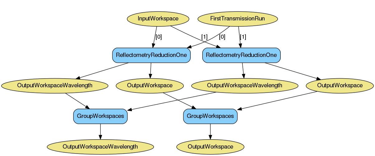
If PolarizationAnalysis = None the reduction stops here. Note that if transmission runs are given in the form of a workspace group, each member in the transmission group will be associated to the corresponding member in the input workspace group, i.e., the first item in the transmission group will be used as the transmission run for the first workspace in the input workspace group, the second element in the transmission group will be used as the transmission run for the second workspace in the input workspace group, etc. This is also illustrated in the diagram above, where [0] represents the first element in a workspace group, [1] the second element, etc. If transmission runs are provided as matrix workspaces the specified runs will be used for all members of the input workspace group.
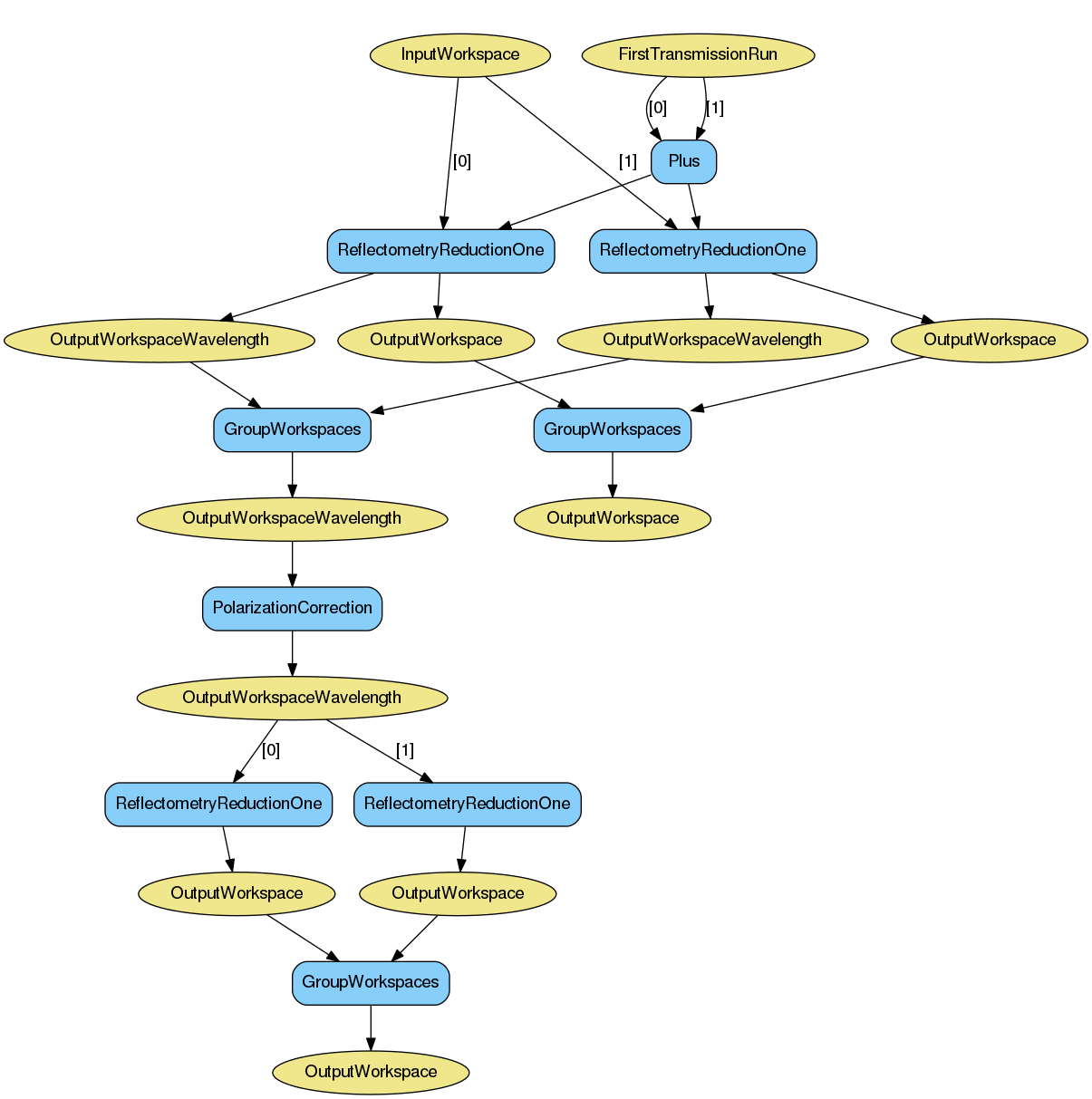
If PolarizationAnalysis is set to PA or PNR the reduction continues and polarization corrections will be applied to the output workspace in wavelength. The algorithm will use the properties PolarizationAnalysis, CPp, CAp, CRho and CAlpha to run PolarizationCorrection v1. The result will be a new workspace in wavelength, which will override the previous one, that will be used as input to ReflectometryReductionOne v2 to calculate the new output workspaces in Q, which in turn will override the existing workspaces in Q. Note that if transmission runs are provided in the form of workspace groups, the individual workspaces will be summed to produce a matrix workspace that will be used as the transmission run for all items in the input workspace group, as illustrated in the diagram below (note that, for the sake of clarity, the rebinned output workspace in Q, OutputWorkspaceBinned, is not represented but it is handled analogously to OutputWorkspace).
This is version 2 of the algorithm. For version 1, please see here.
Note
To run these usage examples please first download the usage data, and add these to your path. In MantidPlot this is done using Manage User Directories.
Example - Basic reduction with no transmission run, polynomial corrections will be automatically applied
run = Load(Filename='INTER00013460.nxs')
IvsQ, IvsQ_unbinned, IvsLam = ReflectometryReductionOneAuto(InputWorkspace=run, ThetaIn=0.7)

print("{:.5f}".format(IvsLam.readY(0)[175]))
print("{:.5f}".format(IvsLam.readY(0)[176]))
print("{:.5f}".format(IvsQ_unbinned.readY(0)[106]))
print("{:.5f}".format(IvsQ_unbinned.readY(0)[107]))
print("{:.5f}".format(IvsQ.readY(0)[13]))
print("{:.5f}".format(IvsQ.readY(0)[14]))
Output:
0.00441
0.00462
0.63441
0.41079
0.44792
0.23703
Example - Basic reduction with a transmission run
run = Load(Filename='INTER00013460.nxs')
trans = Load(Filename='INTER00013463.nxs')
IvsQ, IvsQ_unbinned, IvsLam = ReflectometryReductionOneAuto(InputWorkspace=run, FirstTransmissionRun=trans, ThetaIn=0.7)

print("{:.5f}".format(IvsLam.readY(0)[164]))
print("{:.5f}".format(IvsLam.readY(0)[164]))
print("{:.5f}".format(IvsQ_unbinned.readY(0)[96]))
print("{:.5f}".format(IvsQ_unbinned.readY(0)[97]))
print("{:.5f}".format(IvsQ.readY(0)[5]))
print("{:.5f}".format(IvsQ.readY(0)[6]))
Output:
0.00338
0.00338
1.16756
0.89144
1.46655
1.41327
Example - Reduction overriding some default values
run = Load(Filename='INTER00013460.nxs')
IvsQ, IvsQ_unbinned, IvsLam = ReflectometryReductionOneAuto(InputWorkspace=run, ThetaIn=0.7, DetectorCorrectionType="RotateAroundSample", MonitorBackgroundWavelengthMin=0.0, MonitorBackgroundWavelengthMax=1.0)

print("{:.5f}".format(IvsLam.readY(0)[175]))
print("{:.5f}".format(IvsLam.readY(0)[176]))
print("{:.5f}".format(IvsQ_unbinned.readY(0)[106]))
print("{:.5f}".format(IvsQ_unbinned.readY(0)[107]))
print("{:.5f}".format(IvsQ.readY(0)[5]))
print("{:.5f}".format(IvsQ.readY(0)[6]))
Output:
0.00441
0.00462
0.64231
0.41456
0.51029
0.52241
Categories: Algorithms | Reflectometry\ISIS
C++ source: ReflectometryReductionOneAuto2.cpp (last modified: 2018-03-07)
C++ header: ReflectometryReductionOneAuto2.h (last modified: 2018-03-07)