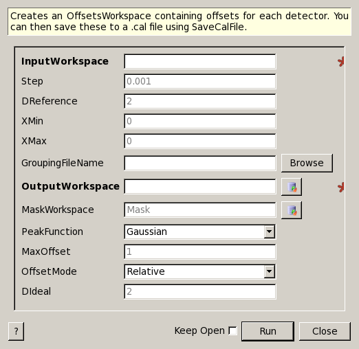
GetDetectorOffsets dialog.
Table of Contents
Creates an OffsetsWorkspace containing offsets for each detector. You can then save these to a .cal file using SaveCalFile.
| Name | Direction | Type | Default | Description |
|---|---|---|---|---|
| InputWorkspace | Input | MatrixWorkspace | Mandatory | A 2D workspace with X values of d-spacing |
| Step | Input | number | 0.001 | Step size used to bin d-spacing data |
| DReference | Input | number | 2 | Center of reference peak in d-space |
| XMin | Input | number | 0 | Minimum of CrossCorrelation data to search for peak, usually negative |
| XMax | Input | number | 0 | Maximum of CrossCorrelation data to search for peak, usually positive |
| GroupingFileName | Input | string | Optional: The name of the output CalFile to save the generated OffsetsWorkspace. Allowed extensions: [‘.cal’] | |
| OutputWorkspace | Output | OffsetsWorkspace | An output workspace containing the offsets. | |
| MaskWorkspace | Output | MatrixWorkspace | Mask | An output workspace containing the mask. |
| PeakFunction | Input | string | Gaussian | The function type for fitting the peaks. Allowed values: [‘BackToBackExponential’, ‘Bk2BkExpConvPV’, ‘DeltaFunction’, ‘ElasticDiffRotDiscreteCircle’, ‘ElasticDiffSphere’, ‘ExamplePeakFunction’, ‘Gaussian’, ‘IkedaCarpenterPV’, ‘Lorentzian’, ‘PseudoVoigt’, ‘Voigt’] |
| MaxOffset | Input | number | 1 | Maximum absolute value of offsets; default is 1 |
| OffsetMode | Input | string | Relative | Whether to calculate a relative or absolute offset. Allowed values: [‘Relative’, ‘Absolute’] |
| DIdeal | Input | number | 2 | The known peak centre value from the NIST standard information, this is only used in Absolute OffsetMode. |
This algorithm requires a workspace that is both in d-spacing, but has also been preprocessed by the CrossCorrelate v1 algorithm. In this first step you select one spectrum to be the reference spectrum and all of the other spectrum are cross correlated against it. Each output spectrum then contains a peak whose location defines the offset from the reference spectrum.
The algorithm iterates over each spectrum in the workspace and fits a PeakFunction (default is a Gaussian function) to the reference peaks. The fit is used to calculate the centre of the fitted peak, and the offset is then calculated as:

This is then written into a .cal file for every detector that contributes to that spectrum. All of the entries in the cal file are initially set to both be included, but also to all group into a single group on DiffractionFocussing v2. The CreateCalFileByNames v1 algorithm can be used to alter the grouping in the cal file.
import os

# Create a workspace with a Gaussian peak in the centre.
ws = CreateSampleWorkspace(Function='User Defined',UserDefinedFunction='name=Gaussian,Height=1,PeakCentre=10,Sigma=1',XMin=0,XMax=20,BinWidth=0.1)
ws.getAxis(0).setUnit( 'dSpacing' )

# Generate a file path to save the .cal file at.
calFilePath = os.path.expanduser( '~/MantidUsageExample_CalFile.cal' )

# Run the algorithm
msk = GetDetectorOffsets(ws,0.001,10.0,0, 10, calFilePath)

# Read the saved .cal file back in
f = open( calFilePath, 'r' )
file = f.read().split('\n')
f.close()

# Print out first 10 lines of the file
print file[0][:55],'...'
for line in file[1:10]:
    print line
# Calibration file for instrument basic_rect written on ...
# Format: number    UDET         offset    select    group
        0            100     -0.0014265       1       1
        1            101     -0.0014265       1       1
        2            102     -0.0014265       1       1
        3            103     -0.0014265       1       1
        4            104     -0.0014265       1       1
        5            105     -0.0014265       1       1
        6            106     -0.0014265       1       1
        7            107     -0.0014265       1       1
Categories: Algorithms | Diffraction\Calibration