You will need to run a sample which will create good clean peaks at known reference dSpacing positions. To get a good calibration you will want good statistics on this calibration data.
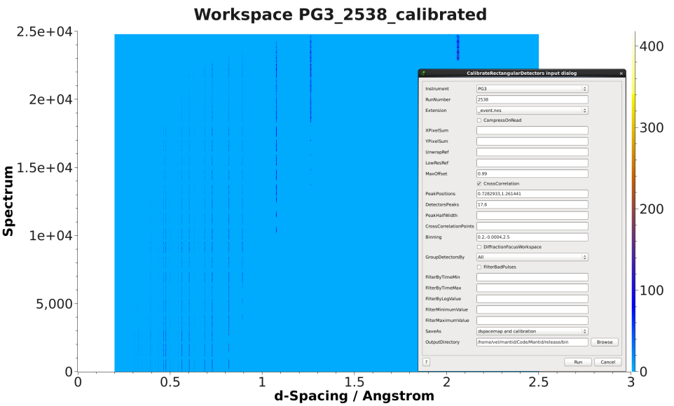
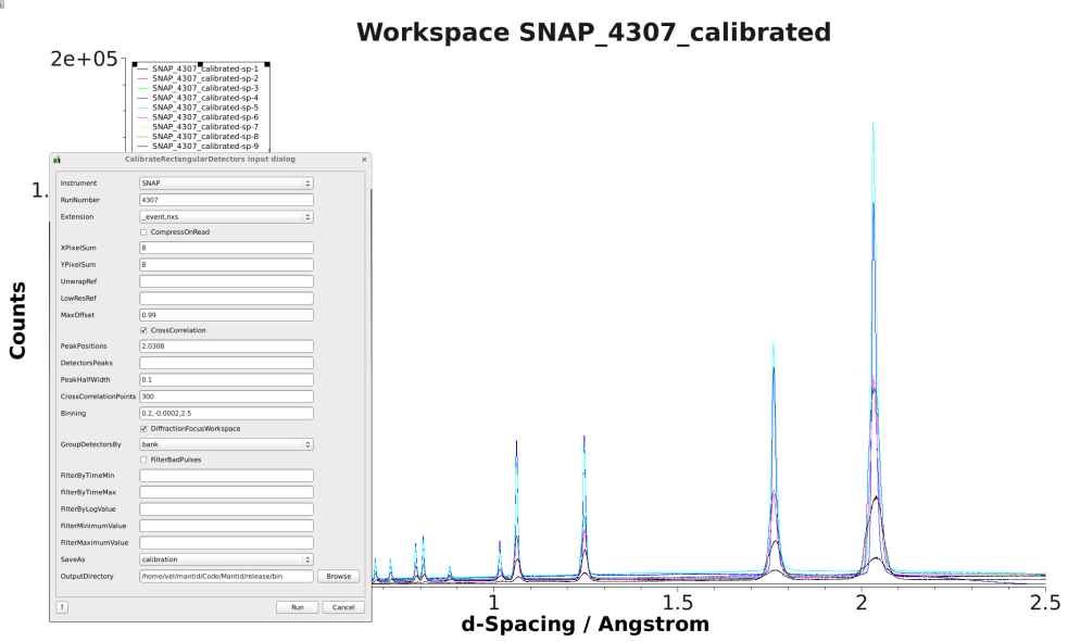
If you are trying to calibrate an instrument that uses rectangular detectors the SNS have created a single algorithm to do all of this for you, CalibrateRectangularDetectors. At the time of writing this only supports SNS instruments, but look at the algorithm link for an up to date list.
- Load the calibration data using Load
- Convert the X-Units to d-spacing using ConvertUnits
- Run Rebin to set a common d-spacing bin structure across all of the spectra, you will need fine enough bins to allow fitting of your peak. Perhaps 0.001 as a rebin step, whatever you choose, make a note of it you may need it later.
- Take a look at the data using the SpectrumVeiwer or a color map plot, find the workspace index of a spectrum that has the peak close to the known reference position. This will be the reference spectra and will be used in the next step.
- Here the steps can split depending on whether you are calibrating on a single peak, or a range of peaks
- Single Peak calibration (this requires the same peak in all detectors)
- Cross correlate the spectrum with CrossCorrelate, enter the workspace index as the ReferenceSpectra you found in the last step.
- Run GetDetectorOffsets, the InputWorkspace if the output from CrossCorrelate. Use the rebinning step you made a note of in step 3 as the step parameter, and DReference as the expected value of the reference peak that you are fitting to. XMax and XMin define the window around the reference peak to search for the peak in each spectra, if you find that some spectra do not find the peak try increasing those values.
- The output is an OffsetsWorspace, that can be used directly in DiffractionFocussing, or saved using SaveCalFile. You can also save it as a CalFile from GetDetectorOffsets, by defining the GroupingFileName parameter.
- Multi Peak Calibration (This is less well tested)
If you do not have a single peak in all detectors, but a range of known peaks across detectors you can try this approach. Another possible approach is to perform the single peak calibration across sections of the instrument with different reference peaks and combine the output calibration.
- Run GetDetOffsetsMultiPeaks, the Input workspace is the one from step 3 earlier. For DReference you can enter a comma seperated list of the d-spacing values of the known peaks.
- The output is an OffsetsWorspace, and a workspace with the number of peaks found in each spectra, The output offsets workspace that can be used directly in DiffractionFocussing, or saved using SaveCalFile. You can also save it as a CalFile from GetDetOffsetsMultiPeaks, by defining the GroupingFileName parameter.