\(\renewcommand\AA{\unicode{x212B}}\)
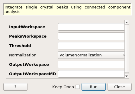
IntegratePeaksUsingClusters dialog.
Table of Contents
| Name | Direction | Type | Default | Description |
|---|---|---|---|---|
| InputWorkspace | Input | IMDHistoWorkspace | Mandatory | Input md workspace. |
| PeaksWorkspace | Input | PeaksWorkspace | Mandatory | A PeaksWorkspace containing the peaks to integrate. |
| Threshold | Input | number | Mandatory | Threshold signal above which to consider peaks |
| Normalization | Input | string | VolumeNormalization | Normalization to use with Threshold. Defaults to VolumeNormalization to account for different binning. Allowed values: [‘NoNormalization’, ‘VolumeNormalization’, ‘NumEventsNormalization’] |
| OutputWorkspace | Output | PeaksWorkspace | Mandatory | An output integrated peaks workspace. |
| OutputWorkspaceMD | Output | IMDHistoWorkspace | Mandatory | MDHistoWorkspace containing the labeled clusters used by the algorithm. |
Integrates arbitrary shaped single crystal peaks defined on an MDHistoWorkspace using connected component analysis to determine regions of interest around each peak of the PeaksWorkspace. The output is an integrated PeaksWorkspace as well as an image containing the labels assigned to each cluster for diagnostic and visualisation purposes.
The algorithm makes no assumptions about Peak shape or size and can therefore be used where integration over defined shapes IntegratePeaksMD v2 and IntegrateEllipsoids v1, for example, will not work.
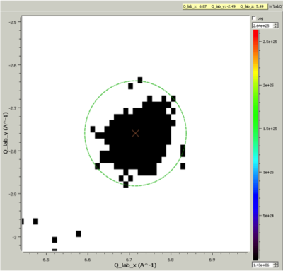
Cluster Label region displayed in the SliceViewer. Peak centre is marked with an X. The green circle illustrates the integration region used by IntegratePeaksMD v2
A threshold for the Peak should be defined below which, parts of the image are treated as background. The normalization method in combination with the threshold may both be used to define a background. We suggest keeping the default of VolumeNormalization so that changes in the effective bin size do not affect the background filtering. NaN is always considered background.
This algorithm uses an imaging technique, and it is therefore important that the MDHistoWorkspace you are using is binned to a sufficient resolution via BinMD v1. You can overlay the integrated peaks workspace in the Sliceviewer over the generated Cluster Labeled OutputWorkspaceMD to see what the iteration region used for each peak amounts to.
It is suggested that you initially run the algorithm on a coarse image. This will help you tune the Threshold parameters. The algorithm generates a large memory footprint, so it is suggested that you keep the initial image small, and run on hardware with sufficient memory to store multiple workspace of equal size to the input MDWorkspace (generated as part of the connected component analysis).
The algorithm will generate warning. There are three main warning to know about.
The algorithm will warn about unreachable peaks (off the image). This may be because the peaks detected were off the edge of the detector, or because the image was cropped in BinMD in such a way that that part of the detector/TOF space is no longer accessible.
This is because the input PeaksWorkspace has peaks that do not align with peaks in the image. The error could either be on the side of the input PeaksWorkspace (spurious peaks), or of the MDHistoWorkspace generated as part of processing. One thing to verify is that the combination of Threshold and Normalization input parameters are not so low that they are treating genuine peaks in the image as background.
This means overlapping peaks in the image. This is a problem because both peaks will be given an integrated value that is the sum of the entire cluster. You may need to increase the Threshold parameter to resolve this problem.
For more in-depth analysis, the algorithm will produce debug log messages.
Example - Simple Integration of TOPAZ data
import os
def make_input_workspaces():
    instrument_path = os.path.join(config.getInstrumentDirectory(), 'SXD_Definition.xml')
    sxd = LoadEmptyInstrument(Filename=instrument_path)
    # Set lattice parameters
    SetUB(sxd, 5.6, 5.6, 5.6, 90, 90, 90)
    # Predict peaks
    predicted = PredictPeaks(sxd)
    # Keep every 20th predicted peak for speed
    rows_to_delete = set(range(predicted.getNumberPeaks())) - set([i for i in range(predicted.getNumberPeaks()) if i % 20 == 0])
    DeleteTableRows(predicted, Rows=list(rows_to_delete))

    # Set the Frame to QLab
    mdws = CreateMDWorkspace(Dimensions=3, Extents='-10,10,-10,10,-10,10',
                                           Names='Q_lab_x,Q_lab_y,Q_lab_z', Frames = "QLab,QLab,QLab",
                                           Units='U,U,U')
    qlab = predicted.column('QLab')
    peak_radius = 0.1
    n_events = 1000
    for coords in qlab:
        FakeMDEventData(InputWorkspace=mdws, PeakParams=[n_events, coords.X(), coords.Y(), coords.Z(), peak_radius])
    # Create MDHisto workspace
    mdws_binned = BinMD(InputWorkspace=mdws, AlignedDim0='Q_lab_x,-10,10,20', AlignedDim1='Q_lab_y,-10,10,200', AlignedDim2='Q_lab_z,-10,10,200')
    return (predicted, mdws_binned, peak_radius)

predicted, mdws_binned, peak_radius = make_input_workspaces()
# Perform the integration
integrated, clusters = IntegratePeaksUsingClusters(InputWorkspace=mdws_binned, PeaksWorkspace=predicted, Threshold=1e7)
Categories: AlgorithmIndex | MDAlgorithms\Peaks | Crystal\Integration