Beam centre tab#

The beam centre tab allows the position of the beam centre to be set either manually by the user or by running the beam centre finder.
The beam centre finder iteratively locate estimates of the X & Y coordinates of the centre of a scattering pattern.
On LOQ, where the main detector never moves, the beam centre stays fairly constant, typically only ever moving a fraction of a mm as the incident beam size is changed.
On SANS2D, however, it is a completely different story; not only does the detector move in Z but it will often also be offset in X. This means that the beam centre coordinates can vary significantly (10’s of mm) between successive Users and, thus, user files.
Using the Beam Finder on LOQ#
Load the previous user (mask) file (or a proto-user file for the new User).
Load a suitable SANS pattern (eg, the scattering from a calibration standard for the Main detector, or a Glassy Carbon for the HAB).
Under the ‘Analysis details’ tab, limit the wavelength range from 2.2 to 5.0 Angstroms for the Main detector, or 2.2 to 7.0 Angstroms for the HAB. For the HAB, also limit the radius from 35 to 750 mm AND select the HAB detector.
For the Main detector, limit the Q range from 0.029 to 0.149 /Angstrom, and bin it in logarithmic 0.08 steps. For the HAB limit the Q range from 0.22 to 0.8 /Angstrom, and bin it in linear 0.0125 steps.
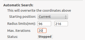
In the ‘Beam Centre’ box under the ‘Geometry’ tab, ensure the starting position is ‘Current’, that the radius limits are 96 & 216 for the Main detector or 96 & 750 for the HAB, and set the number of iterations for the search algorithm to 20.
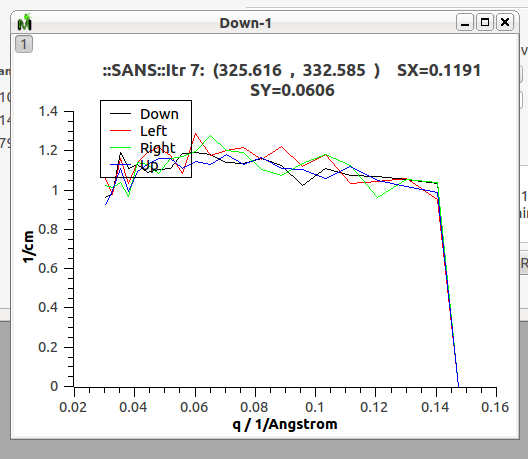
Run the beam centre finder. A good solution is one in which all 4 curves on the plot overlap one another. Typically it will converge before the iterations are exhausted.
Edit the final beam centre coordinates into the user file SET CENTRE and SET CENTRE/HAB.
Note: The Mantid routine particular seems to converge to what it considers an acceptable result slightly too early (perhaps 0.5 mm different).
This is under investigation. In the meantime a good workaround is to examine the X & Y residual values and note down the X & Y coordinates with the lowest residuals (these will likely be on different iterations). Edit these coordinates into the user file, reload it, and re-run the beam centre finder (remembering that any changes you made in Analysis Details will need to be reset).
Repeat this process a couple of times and you will get good beam centre coordinates.
Using the Beam Finder on SANS2D#
The search algorithm typically requires starting coordinates that are within 20 mm of the final iterated best estimates in order to work properly. This may sound generous, but on a detector 980 mm square this tolerance actually translates to about 4%!
Obtaining reliable starting coordinates for the centre search is therefore paramount.
The following procedure seems to work:
Load the most recent user (mask) file (or a proto-user file for the new User).
Load a suitable SANS pattern (eg, the scattering from a calibration standard).
‘Show Instrument’ on the SANS run.
In ‘Pick’ mode, using the cursor and the physical coordinates of the pixels displayed at the bottom of the screen, work out the X & Y displacements of the centre of the pattern from the origin of the display (a small square overlaid on the detector pattern). NB: If the Origin appears to have coordinates (0,0,Z) then the user file may already have the correct - or an almost correct - beam centre.
The displacements will be in m, so multiply them by 1000 to convert to mm. Subtract these values from the SET CENTRE X & Y values in the user file and save it. As a guide, the Y-centre will typically be about -170, give or take a few mm.
Under the ‘Run Numbers’ tab, reload the user file.
Under the ‘Analysis Details’ tab, limit the Qx range to a maximum of about 0.15 /Ang and increase the Q binning to improve the data quality, say 12% log bins. It is also a good idea to push out the minimum Q. At 4m, say, from 0.0035 to 0.01 /Angstron, for example.
In the ‘Beam Centre’ box under the ‘Geometry’ tab, ensure the starting position is ‘Current’, that the radius limits are something like 60 & 280, and set the number of iterations for the search algorithm to 2.
Run the beam centre finder. If it looks as if it is starting to converge, increase the number of iterations to between 10 and 20 and re-run it. A good solution is one in which all 4 curves on the plot overlap one another.
Edit the final beam centre coordinates into the user file SET CENTRE.
Description Of Tab#
Centre Position LAB |
The centre position of the low angle bank. The first coordinate is horizontal and the second vertical. These boxes are populated by the user file and the values here are used by the reduction. |
Centre Position HAB |
The centre position of the high angle bank. The first coordinate is horizontal and the second vertical. These boxes are populated by the user file and the values here are used by the reduction. |
Minimum radius limit |
The minimum radius of the region used to ascertain centre position. |
Maximum radius limit |
The maximum radius of the region used to ascertain centre position. |
Minimum Q limit |
The minimum Q of the region used to ascertain centre position. |
Maximum Q limit |
The maximum Q of the region used to ascertain centre position. |
Max iterations |
The maximum number of iterations the algorithm will perform before concluding its search. |
Tolerance |
If the centre position moves by less than this in an iteration the algorithm will conclude its search. |
General Options |
The Verbose option will store the output workspaces from all iterations in memory. The Initial COM option will if checked use a centre of mass estimate as the starting point of the search rather than the user input value. |
Left/Right |
Controls whether the beam centre finder searches for the centre in the left/right and up/down directions. |
Run |
Runs the beam centre finder the boxes 1 and 2 are updated with new values upon completion. |